6
PACS
®
Command (RD#B2):
51 00 B2
Returned Data (example):
09 A0
AVERAGE MOTOR CURRENT
(DHC-400 only)
00B4 DOUB
The Average Motor Current parameter is a
measure of the average current drawn by the motor during
the past 3 to 4 minutes. This parameter is useful in
monitoring the drain on the DC power source; particular to
batteries, this parameter can be used to project how long a
given battery charge might last. This parameter is a DOUB
byte value that is scaled from 0 to 2500 representing 0 to
25.00A. In the following example, $009B (155 decimal)
represents a current of 1.55A.
PACS
®
Command (RD#B4):
51 00 B4
Returned Data (example):
00 9B
MOTOR CURRENT TRIP SETTING
(DHC-400 only)
00B6 DOUB
The DHC-400 features a current trip function that
can be used in place of, or in addition to, torque switches
that are commonly used in actuators. The trip current is set
by adjusting the on-board trim pot. The setting cannot be
overwritten, but can be read. The Trip Current Setting
parameter is a DOUB byte value that is scaled from 0 to
1200 representing 0 to 12.00A. In the following example,
$0140 (320 decimal) represents a current trip setting of
3.20A.
PACS
®
Command (RD#B6):
51 00 B6
Returned Data (example):
01 40
POSITION
00B8 DOUB
In order to position an automated valve to a desired
position (according to the analog or digital command
input), the DHC controller uses a feedback potentiometer to
monitor the position of the actuator's output shaft that
connects to the valve stem. This parameter is a DOUB byte
value that is automatically scaled from 0 to 10000 which
represents 0% to 100% open. In the following example,
$0D96 (3478 decimal) represents a position of 34.78%
open.
PACS
®
Command (RD#B8):
51 00 B8
Returned Data (example):
0D 96
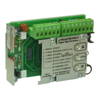
When setting up the DHC controller, the user can
set the closed position, using the CLOSE mode, to any
point within the range of the actuator. Likewise, the open
position can be set to any desired point using the OPEN
mode. The DHC automatically scales the Position
parameter to associate 0% with the closed position, and
100% with the open position.
If the feedback potentiometer is operated outside of
its range (usually due to incorrect installation), or if it incurs
a failure (broken connection, shorted connection, etc.), the
Position parameter will either read 0% or 100%. When this
occurs, the FAULT light on the DHC controller will flash
and the outputs to the actuator are turned off. The
automation system can monitor this fault condition using
the Alarm Flags parameter.
ALARM FLAGS 2
(DHC-400 only)
00BD DOUB
The Alarm Flags 2 parameter is a SING byte
value, where each bit corresponds to one of the alarm
conditions monitored by a DHC-400 controller. These are
in addition to the alarm conditions that are monitored for
the Alarm Flags parameter. A bit value of "1" indicates
that the associated alarm condition has been detected, while
a "0" bit indicates that no alarm condition has been
detected. These alarm conditions cause a fault, where the
DHC-400 controller disables the outputs to the actuator and
sets the FAULT lights on the control panel accordingly.

 Loading...