9
CYCLES OF OPERATION
00C6 QUAD
While the Hours of Operation parameter can
provide a measure of how long an actuator/valve has been
in service, the wear on the mechanical components in an
actuator and valve is better measured by how often the
valve is moved. The Cycles of Operation parameter is a
cycle counter that indicates how many times the actuator
was switched from off to on by the DHC controller. The
parameter is set to zero at the time of manufacture and
cannot be changed or reset by the user.
This parameter is a QUAD byte value that ranges
from 0 to 4,294,967,295 representing the number of cycles.
In the following example, $001A5E06 (1728006 decimal)
indicates that the DHC controller turned the actuator on
1,728,006 times.
PACS
®
Command (RQ#C6):
52 00 C6
Returned Data (example):
00 1A 5E 06
ALARM FLAGS
00CA SING
The Alarm Flags parameter is a SING byte value,
where each bit corresponds to one of the alarm conditions
monitored by the DHC controller. A bit value of "1"
indicates that the associated alarm condition has been
detected, while a "0" bit indicates that no alarm condition
has been detected. The bit assignment for each alarm
condition is shown below:
7 6 5 4 3 2 1 0
X
loss of command
X
feedback potentiometer alarm
X
motor alarm (M1 stall)
X
motor alarm (M2 stall)
X
open limit switch alarm
X
close limit switch alarm
X
aux open limit alarm
X
aux close limit alarm
Bits 0-5 are alarm conditions that cause a fault, where the
DHC controller disables the outputs to the actuator. A
FAULT condition is also indicated on the DHC control
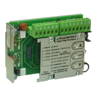
panel (see Figures 1 and 2).
In the following example, $81 (1000 0001 binary) indicates
that an "aux close limit alarm" and a "loss of command"
alarm have been detected.
PACS
®
Command (RS#CA):
50 00 CA
Returned Data (example):
81
Bit 0 - "loss of command"
When configured for a 4-20mA, 1-5V, 2-10V
(DHC-400 only), or Digital command type, the
DHC controller can detect when the command
signal has been lost and sets this bit accordingly.
For a 0-5V or 0-10V command type, a loss of
command cannot be detected and this bit will
always read "0". The DHC can also be configured
to run to the open or closed position when a "loss
of command" alarm is detected.
The DHC-100, 200, and 300 Series controllers
detect a loss of command when the analog input
signal goes below its minimum value (e.g., less
than 4mA for 4-20mA command type) or above its
maximum value (e.g., more than 20mA for a 4-
20mA command type). The DHC-400 differs in
that it detects a command out of range alarm for
signals that are above the maximum value (see
Alarm Flags 2 ($00BD) parameter).
Bit 1 - "feedback potentiometer alarm"
If the feedback potentiometer, which provides
position information to the DHC, is operated
outside of its range, bit 1 will be set to "1". The out
of range condition is detected when the
potentiometer reaches less than 5%, or more than
95%, of its resistance value. A broken or shorted
wire will cause the feedback signal to be at one of
the extremes, and therefore is detected as well.
Bit 2 - "motor alarm (M1 stall)"
When the DHC controller turns on its M1 output to
run the actuator and does not detect any motion
after a period of time, bit 2 will be set to "1". This
indicates that the DHC has detected a stall in the
M1 direction. Since the DHC-400 measures motor
current, this bit is set if the current was greater than
0.5A, otherwise bit 2 of the Alarm Flags 2
($00BD) parameter is set. Whether the M1
direction is toward open or closed depends on
where those positions have been set. When the
DHC is operated in the manual mode from its
control panel (see Figure 1), the ▲ button turns on
the M1 output.

 Loading...