21
SECTION V
APPLICATION INFORMATION
BUS TIMING
A Modbus serial line bus consists of one master
device and at least one slave device, but not more than 247
slave devices. Each slave device must be configured for a
unique node address (1 to 247), while the master device
does not have a node address. All communications on the
bus are controlled by the master device, where the master
transmits a requesting ADU addressed to a specific node, or
slave device, and then waits for a reply, called the
responding ADU, from the addressed node.
If the addressed node does not exist on the bus, or
the specific slave device encountered a problem (such as
power loss, parity error, etc.), no response from the
addressed node will be forthcoming. In this case, the
master will need to know how much time the specific slave
device needs to respond before abandoning the request.
The master device can also send a broadcast
command to all slave devices by sending a requesting ADU
to address zero, where the slave devices execute the
requested function, but do not send a responding ADU. In
this case, the master device will need to know how much
time the slave devices need to process such a request before
sending a new requesting ADU.
For DHC Series controllers equipped with an
OCM-101 Modbus Option Module, the time required to
process a broadcast command is the same as the time
required to send a responding ADU. However, since the
master does not receive a responding ADU for broadcast
commands, it will need to wait the maximum time required,
which is 200msec for the DHC Series controllers.
The 200msec period is actually controlled by the
OCM-101. If the DHC controller cannot complete the task,
the OCM-101 terminates the request and sends no response.
The OCM-101 can be configured via the bus to extend this
period, although it is not necessary with the DHC Series.
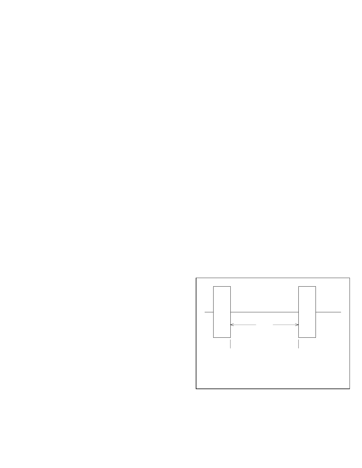
RESPONDIING
ADU
t
RESP
START BIT
REQUESTING
ADU
STOP BIT
Figure 3 - Response Time
Referring to Figure 2, the response time, t
RESP
, is
defined as the time from the last stop bit of the requesting
ADU to the first start bit of the responding ADU.
Response time will vary depending on the Modbus settings
and function codes used. When accessing Modbus