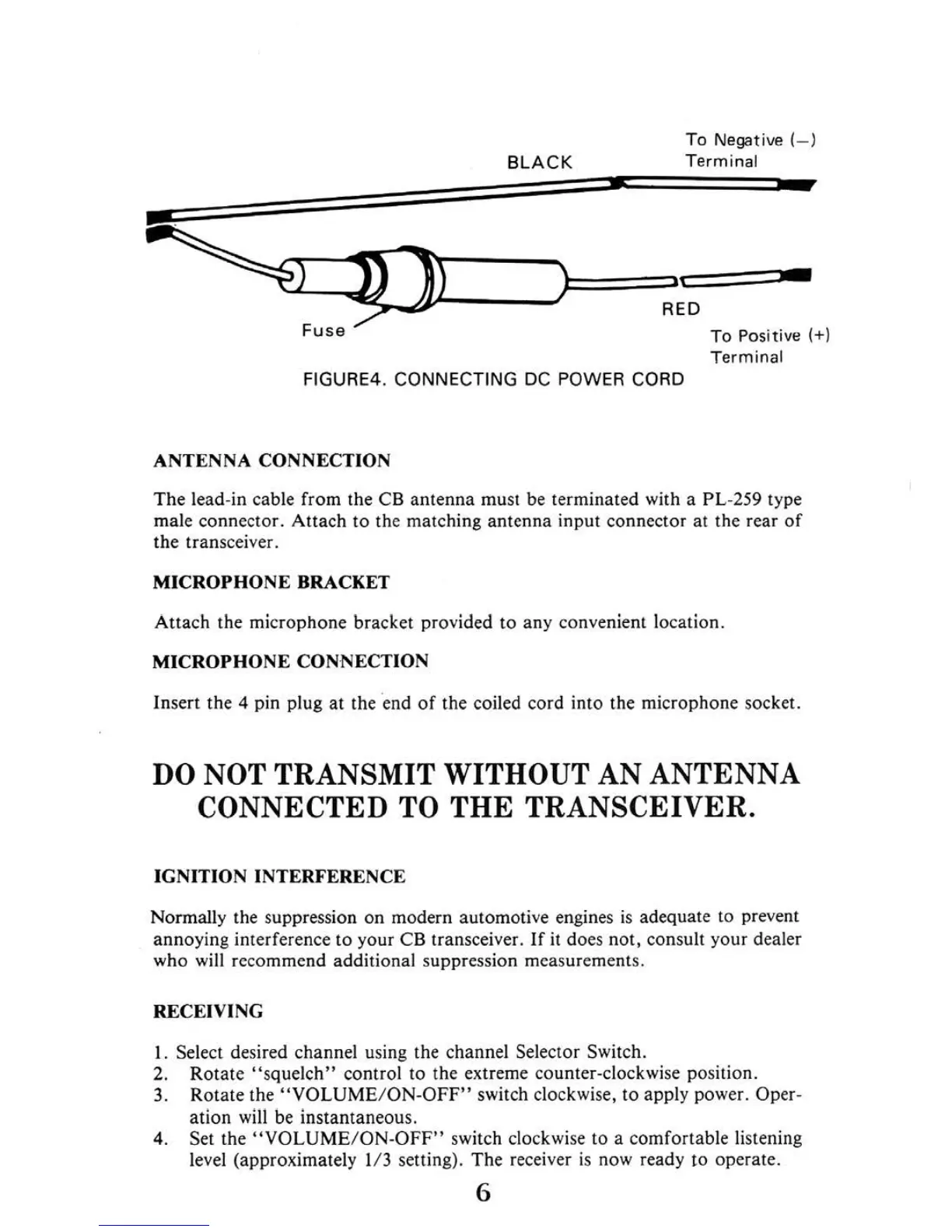
To
Negative(
- )
T
erminal
~
F
use
To
Positive(+
)
FI
GU
RE
4.
CONN ECTING
DC
POW
ER
CO
RD
The lead-in cable from the
CB
antenna must be terminated with a PL-
259
type
male connector. Attach to the matchi
ng
antenna input connector
at
the rear
or
the transceiver.
Attach the microphone bracket provided to any convenient location
MICROPHONE CONNECTION
Insert the 4 pin plug
at
the end
or
the coiled cord into the microphone socket.
DO
NOT TRANSMIT WITHOUT AN AN
TENN
A
CONNECTED TO
THE
TR
A
NSCEI
V
ER.
Normally the suppression on modern automoti
ve
eng
i
nes
is
adequate to prevent
annoying interference to your
CB
transceiver. If
it
does not, consult your dealer
who w
ill
recommend addi1ional suppression measurements.
I. Select desired channel using the channel Selec10r Switch.
2. Rotate
"squelch"
control to the extre
me
counter-clockwise position
3 Rotate the
"VOLUME
/
ON-OFF"
switch clockwi
se,
to apply power. Oper-
at
i
on
will
be
instantaneous.
4. Set the
"VOLUME/ON-OFF"
switch clockwise to a comfortable listening
level (approximately 1
/3
setting). The receiver
is
now ready to operate.