Do you have a question about the Pearce Simpson ST901 and is the answer not in the manual?
Details about RF power output, modulation capability, frequency range, and spurious signal suppression.
Details about receiver sensitivity, image rejection, squelch sensitivity, and selectivity parameters.
Explains the dual-conversion superheterodyne receiver with PLL and ANL.
Details the crystal-controlled transmitter using high-efficiency transistors.
Notes the transceiver's readiness for 12V DC negative ground systems.
Explains how to turn the transceiver on and off using the volume control.
Describes the function of the noise limiter for reducing interference.
Explains how to switch between CB and Public Address modes.
Details how to adjust receiver sensitivity for clear reception.
Explains how the squelch control silences background noise in the receiver.
Describes the clarifier for fine-tuning stations off-frequency for optimal reception.
Explains adjustment of the listening volume for the receiver.
Details how the channel selector sets transmit and receive frequencies simultaneously.
Explains selection of AM, USB, or LSB operating modes.
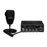
Describes the microphone connector and its wiring for transmit functionality.
Details the recommended plug and impedance for the external speaker jack.
Explains the function of the S/RF meter for indicating signal strength.
Explains the S/TX meter's indication of antenna RF power during transmission.
Describes the TX mode LED indicator that lights up during transmission.
Instructions on how to mount the transceiver using the provided bracket and screws.
Guidance on connecting the power cord to the vehicle's electrical system.
Explains negative and positive ground systems in vehicles and how to identify them.
Specific instructions for connecting the transceiver to a negative ground system.
Instructions for connecting the CB antenna using a PL-259 type connector.
Instructions for attaching the microphone bracket to a convenient location.
Details on plugging the microphone's 4-pin connector into the transceiver's socket.
Discusses potential ignition interference and methods to mitigate it.
Step-by-step guide on how to set up and operate the receiver for listening.
Instructions on how to transmit, use the microphone, and understand transmission etiquette.
Instructions for using the transceiver as a public address amplifier with an external speaker.
| Channels | 23 |
|---|---|
| Modulation Type | AM |
| Type | CB Radio |
| Antenna | External |
| Dimensions | 7.5 x 2.5 x 7.5 inches |