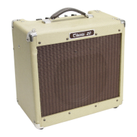
Classic 20 MH
®
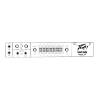
Front Panel
1
2
3
4
5
6
7
8
9
INPUT
Standard 1/4” jack for connection to the output of your guitar or last pedal if using effects before the amp.
Volume
Controls the volume and gain level of the clean channel.
CHANNEL SWITCH
Allows selection of the two different channels. The“IN”position of the switch selects the ‘LEAD’ channel and
the“OUT”position selects the ‘RHYTHM’ channel.
NOTE: Channel selection may also be achieved by using the included footswitch.
If remote selection is desired, the CHANNEL switch (#3) must be set to the“IN” position.
PRE-GAIN
This controls the input volume level of the lead channel and therefore the amount of gain and overdrive.
POST GAIN
This controls the output level when the lead channel is selected. Used to balance the sound between the
two channels.
BASS, MIDDLE & TREBLE EQ controls
These are passive tone controls that regulate the low (bass), mid and high (treble) frequencies of the tone
of BOTH channels.
REVERB
Determines the overall reverb level. Fully counterclockwise will be completely "dry" with no reverb, low
settings will produce subtle reverb and high settings will produce lush ambience. This feature can also be
controlled via the optional remote footswitch.
Pilot Light
Illuminates when AC power is being supplied to the amp and the POWER SWITCH (#11) is set to “ON”.
OUTPUT TUBE STATUS INDICATION (T.S.I.™) LEDS
These are LEDs that light green or red depending on the status of the output tube they are monitoring.
These are merely the visual part of the wider status indication, fault detection and tube protection circuits.
The LEDs T1 and T2 relate to the EL84 power tubes from left to right (when viewed from the front).
The simple explanation of this circuit is that the LED will be green in normal working mode and red in any
other mode, including: Standby, low bias, low current (tube wearing out) or high current fault condition
that has activated in the tube protection circuit.
The more complete explanation is as follows:-
On Standby, the LEDs should be red. This is due to the tubes not yet being fully on.
9
1 2 3 7 8
10 11
6
20W
1W
5W
LIFT
GRND
16
8
20W RMS/ 17.9V RMS
8 MIN.
BUILT UNDER U.S. PATENT NO. 7,145,392
DESIGNED AND
ENGINEERED IN U.S.A.
MADE IN CHINA
PEAVEY ELECTRONICS CORP.
A PRODUCT OF
SEND
RETURN
CHNL/BOOST
GRND
LIFT
OUTPUT
SPKR
DEFEAT
ENABLE
90 WATTS
100V
50/60 Hz
115V
220-230V
FUSE
F2AL/250V
RVRB/LOOP
FOOTSWITCH
EFFECTS
LOOP
SPEAKER
OUT
CLASS 2
WIRING
TM
MSDI
(MIC SIMULATED DIRECT INTERFACE)
RECORD OUT
MICROPHONE SIMULATED
USB AUDIO
VOLUME
CHANNEL
INPUT
T2T1
T.S.I.™
0
1
2
3
4
5
6
7
8
9
10
PRE-GAIN
20 Watt All Tube Guitar Amplifier
Classic 20MH
0
1
2
3
4
5
6
7
8
9
10
POST GAIN
0
1
2
3
4
5
6
7
8
9
10
BASS
0
1
2
3
4
5
6
7
8
9
10
MIDDLE
0
1
2
3
4
5
6
7
8
9
10
TREBLE
0
1
2
3
4
5
6
7
8
9
10
REVERB STANDBY POWER
ONON
0
1
2
3
4
5
6
7
8
9
10
4 5
 Loading...