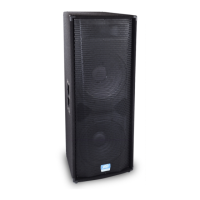
compact, weather-resistant package. The
enclosure utilizes high-impact polypropy-
lene in an injection-molded plastic trape-
zoidal shape, along with a coated perforat-
ed metal grille to offer a cosmetically ele-
gant yet durable system.
The two-way system includes a 12"
Black Widow
®
woofer with a Kevlar
®
impregnated cone and a specially treated
surround, cone and dust cap for excellent
weather resistance. The RX
™
22 compres-
sion driver features a 2" titanium
diaphragm, a patented phase plug
(U.S. Patent 6,064,745), and is coupled
to an extremely smooth and well con-
trolled constant directivity horn, with a
coverage pattern of 90 degrees by 45
degrees that is molded into the enclosure.
Input connection to the system is made
via 1/4" phone jacks (2) or 4-pin Neutrik
®
Speakon
®
connectors. Provisions for
biamplification are made through a 4-pin
Neutrik
®
switching jack. The internal pas-
sive crossover features Sound Guard
™
to
protect the tweeter, and utilizes high per-
formance components and an advanced
topology crossover to provide high power
handling and a smooth yet clear response.
The optimal integration of the crossover
with the selected drivers results in a
smooth frequency response from 75 Hz to
18 kHz.
The free-flow vented cabinet offers
mounting point inserts top and bottom as
well as a molded-in stand adapter for
maximum utility and ease of use.
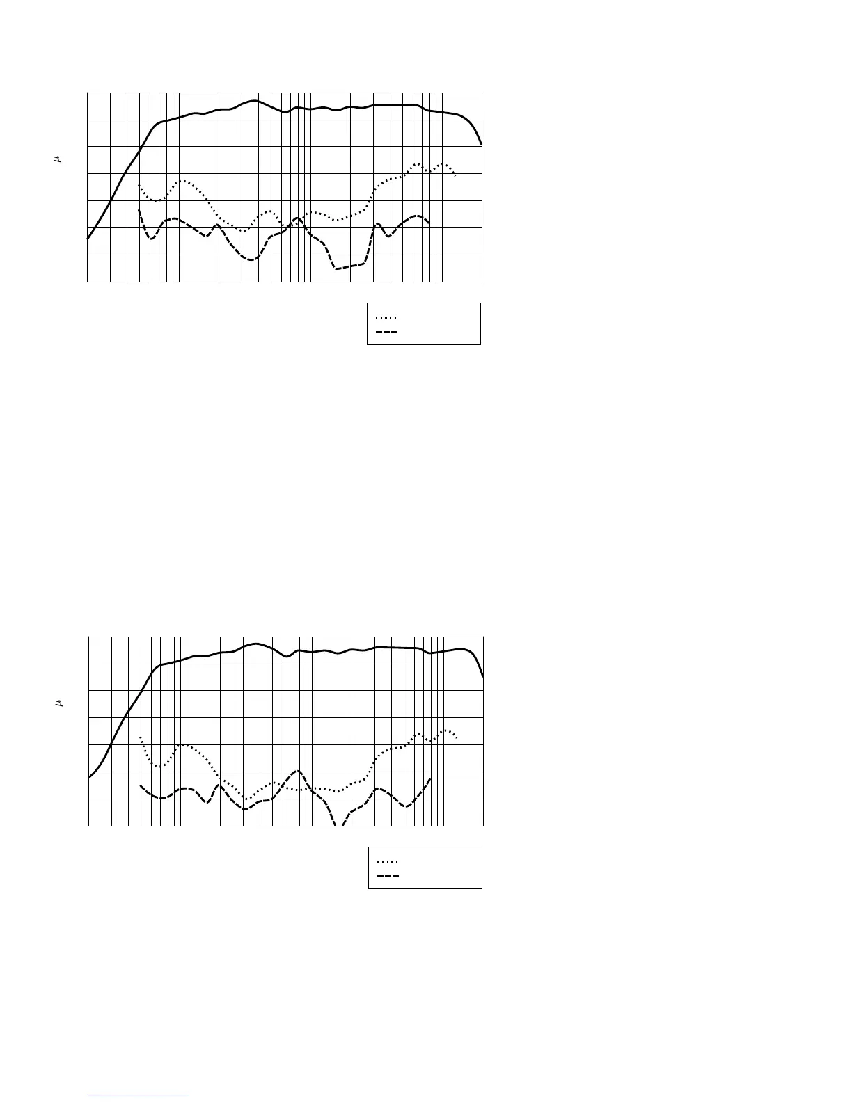
FREQUENCY RESPONSE:
This measurement is useful in deter-
mining how accurately a given unit repro-
duces an input signal. The frequency
response of the Impulse 1012 (8 ohm) is
measured at a distance of 1-meter using a
1 watt (into the nominal impedance)
swept-sine input signal. As shown in
Figure 1, the selected drivers in the
Impulse 1012 (8 ohm) combine to give a
smooth frequency response from 75 Hz -
18 kHz.
DIRECTIVITY:
Beamwidth is derived from the -6 dB
points from the polar plots (Figure 3)
which are measured in a whole space
anechoic environment. Q and Directivity
Index are plotted for the on-axis measure-
ment position. These are specifications
that provide a reference to the coverage
characteristics of the unit. These parame-
ters provide insight for proper placement
and installation in the chosen environ-
ment. The blending of the components of
the Impulse 1012 (8 ohm) exhibit a desir-
able beamwidth and directivity (Figure 3
and 4) suitable for sound reinforcement
applications.
3