10
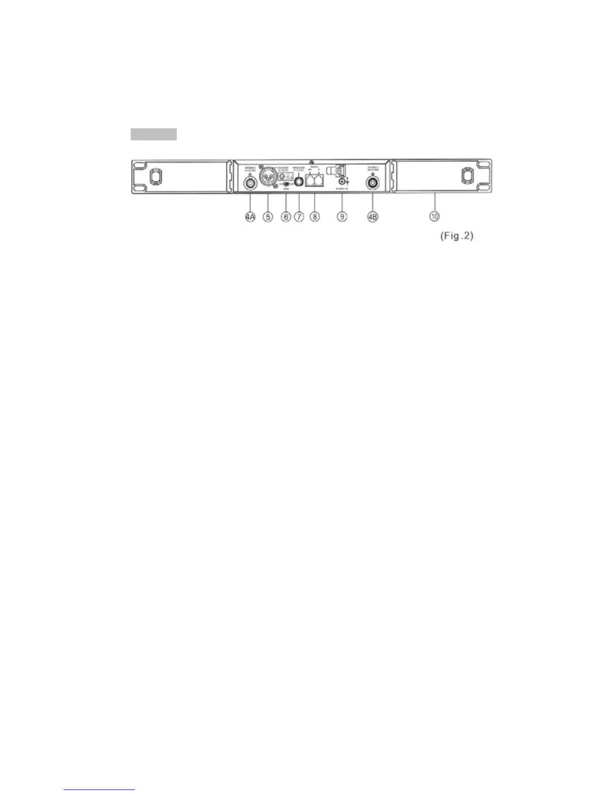
Rear Panel:
(4) Rear Antenna Input Connectors (A/B): Installed with antenna directly. This
connector also provides power for optional antenna booster.
(5) Balanced Audio output Jack: XLR type connector provides a balanced
output signal from the receiver to the mixer.
(6) Line-Level Switch: Used for the selection of either Mic-level or Line-level
output.
(7) Unbalanced Audio output Jack: 1/4" Phone jack provides an unbalanced
signal from the receiver to the mixer or guitar/bass amplifier.
(8) Computer Network Interface connector: Network socket to connect to a
computerized system-monitoring program.
(9) DC Input socket: For 12 volt DC supply. Please note that the polarity of
the center pin in the socket is positive (+),
(10) Rack mount Brackets (OPTIONAL): Allows the installation of the receiver
into an EIA 19" standard rack case.