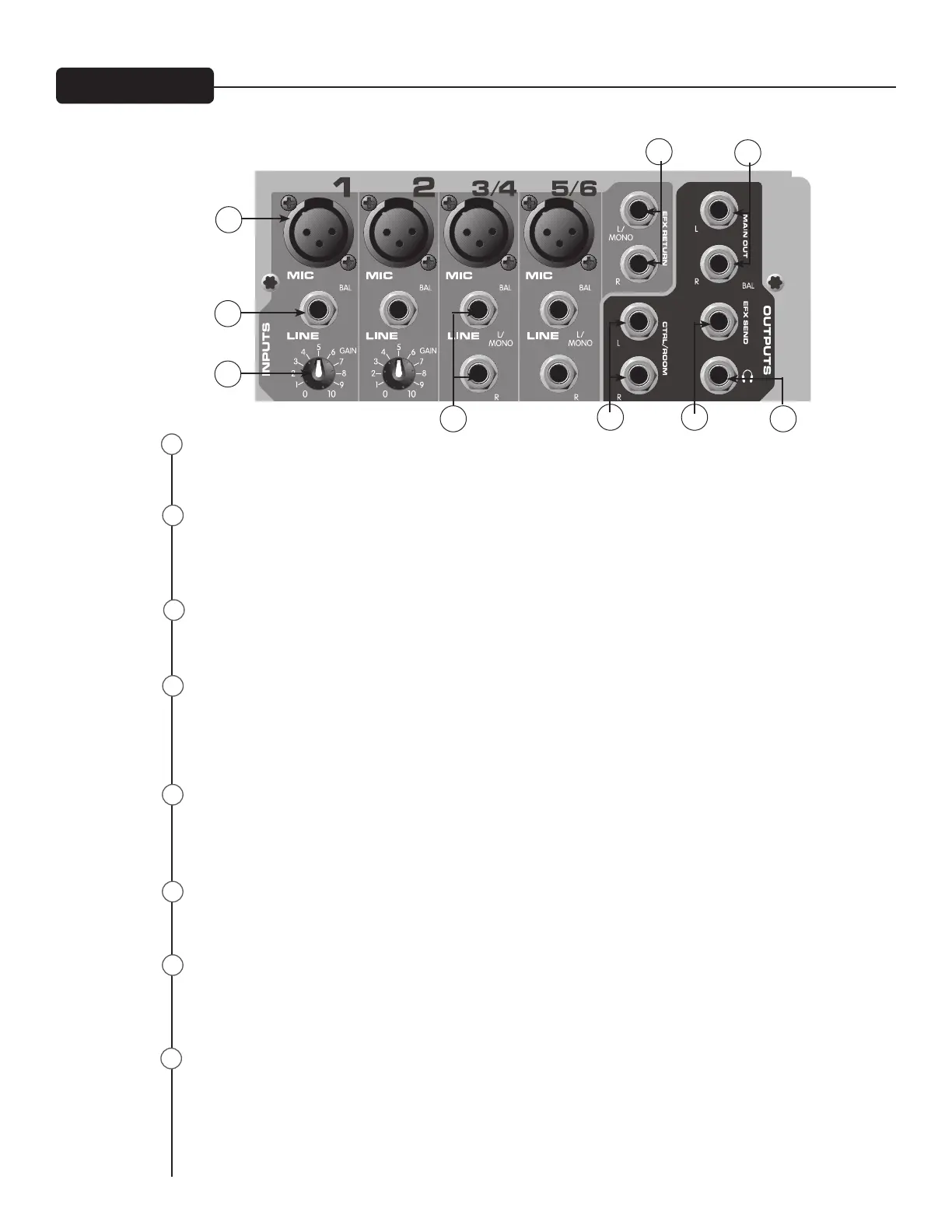
XLR balanced inputs optimized for a microphone or other low impedance source. Pin 2 is the positive
input. Because of the wide range of gain adjustment, signal levels up to +14 dBu can be accommodated.
1⁄4” balanced (TRS) 10 k Ohm impedance input. The tip is the positive input and should be used for un-
balanced inputs. It has 20 dB less gain than the XLR input and does not have phantom power available.
The Mic and Line inputs should not be used simultaneously.
Channels 3 and 4 feature stereo inputs via 1⁄4” inputs and mono XLR inputs. When the 1⁄4" line inputs
are in use‚ the XLR mic input is muted to prevent unwanted noise.
This control establishes the nominal operating level for the channel. The input gain can be adjusted over
a wide range to compensate for soft voices or very loud drums. To maximize the signal-to-noise ratio, the
gain should be set to the proper level with the channel level control (8) set to 0. If the Clip LED comes on
and remains lit, try reducing the gain.
The EFX Return inputs (Left/Mono‚ Right) feature two 1⁄4" TS jacks. These inputs can be used with Tip‚
Ring, Sleeve (TRS) balanced or Tip, Sleeve (TS) unbalanced connectors. The EFX Return is controlled via
the EFX/Return Level Control (19).
The Left/Right Outputs feature two 1⁄4" TRS Z-balanced jacks. These outputs can be used with Tip‚ Ring,
Sleeve (TRS) balanced or Tip, Sleeve (TS) unbalanced connectors.
The Control Room Outputs feature two 1⁄4" TRS Z-balanced jacks. These outputs can be used with Tip‚
Ring Sleeve (TRS) balanced or Tip Sleeve (TS) unbalanced connectors. The Control Room Output Level is
adjusted with the Headphone Level Control (17).
The EFX Send features a 1⁄4" TRS Z-balanced jack in the master section. These outputs can be used with
Tip‚ Ring Sleeve (TRS) balanced or Tip Sleeve (TS) unbalanced connectors. The EFX mix is determined by
the amount of signal being sent to the EFX bus in each channel.
22
26
27
20
21
24
23
25
20
21
23
25
28
2726
22
24

 Loading...