InOut
Out In
CH 2
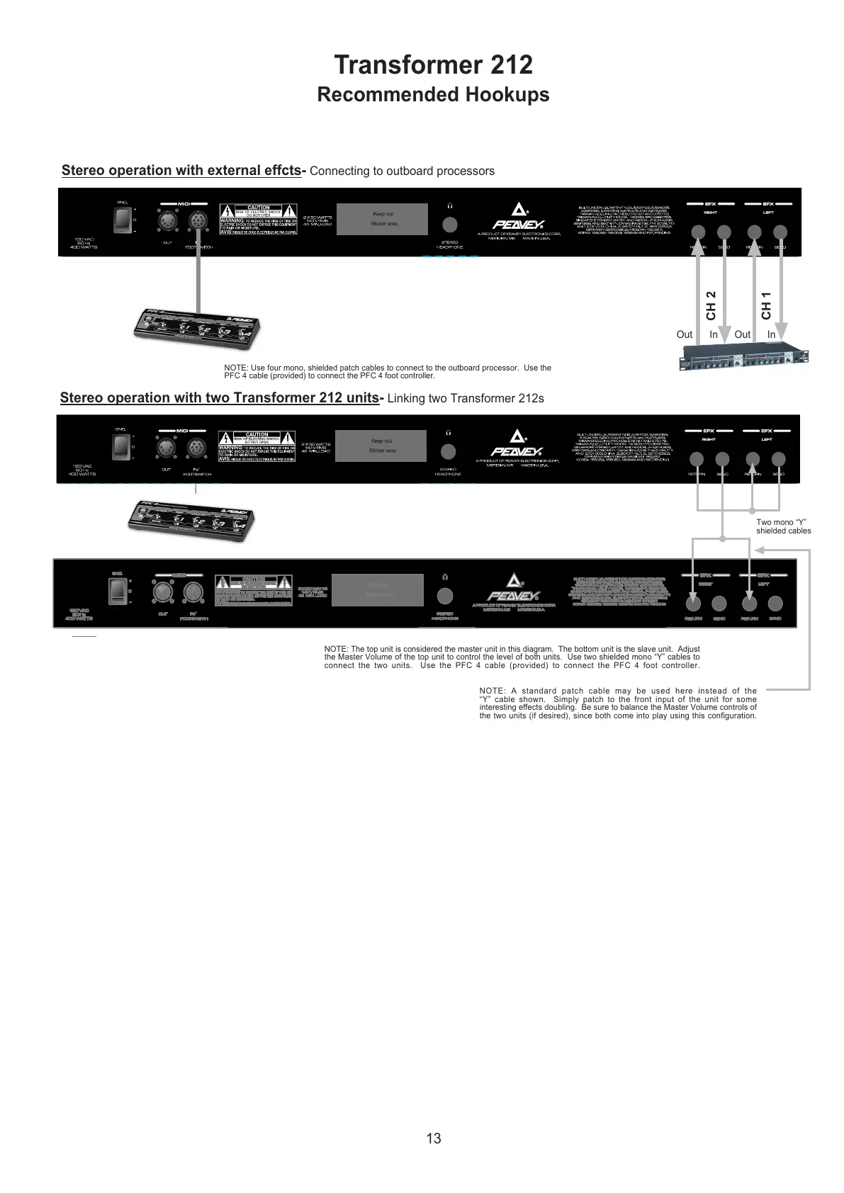
Stereo operation with external effcts- Connecting to outboard processors
Stereo operation with two Transformer 212 units- Linking two Transformer 212s
Two mono “Y”
shielded cables
NOTE: A standard patch cable may be used here instead of the
“Y” cable shown. Simply patch to the front input of the unit for some
interesting effects doubling. Be sure to balance the Master Volume controls of
the two units (if desired), since both come into play using this configuration.
NOTE: Use four mono, shielded patch cables to connect to the outboard processor. Use the
PFC 4 cable (provided) to connect the PFC 4 foot controller.
NOTE: The top unit is considered the master unit in this diagram. The bottom unit is the slave unit. Adjust
the Master Volume of the top unit to control the level of both units. Use two shielded mono “Y” cables to
connect the two units. Use the PFC 4 cable (provided) to connect the PFC 4 foot controller.
CH 1
 Loading...