UMA
™
752 MIXER/AMPLIFIERSpecifications
Master level control
Input channel signal level indicators:
(signal presence = green; signal peak
= red)
Input channel mute status
Power amplifier signal presence
indicator
SPS
™
indicator
Power on indicator
RReeaarr ppaanneell ccoonnttrroollss::
Module input level control use with
MMA input modules only
Channel 1 sensitivity switch
Channel 1 mute bus assign switch
Mute 2 threshold control
Channel 2 sensitivity switch
Channel 2 mute bus assign switch
Channel 4 output level control
Loop switch
Power switch
MMuuttiinngg::
Mute 1: MMA input module overrides
Ch 1 through 4
Mute 2: Ch 1 overrides Ch 2 through 4
with adjustable threshold control range
from OFF to 100 mV (TEL) or 1 mV (MIC)
OOtthheerr ffeeaattuurreess::
Remote volume control (RVC) via screw
terminals
• 10 k Ohms approximately 30 dB
attenuation
• 100 k Ohms approximately 60 dB
attenuation
Mute 1 and mute 2 bus activation with
switch contact closure via screw
terminals
24 V DC phantom power on MIC inputs
PPoowweerr rreeqquuiirreemmeennttss::
180 Watts, 120 V AC, 60 Hz
DDiimmeennssiioonnss::
19" x 13.25" x 3.45" with rack ears
(483 mm x 337 mm x 88 mm)
17" x 13.25" x 3.45" without rack ears
(432 mm x 337 mm x 88 mm)
WWeeiigghhtt::
23.8 lbs. (11 kg)
CCoolloorr::
Black
FFeeaattuurreess
• Up to five input channels
• One electronically balanced Mic/Tel
input – telephone input with 600 Ohm
transformer balanced for paging
• One electronically balanced Mic/Line
input
• Two electronically balanced Line inputs
• One plug-in module port allows for any
single-space MMA
™
module
• Rear-panel input level control for
optional MMA input module
• Priority/Muting system with internal
signal override, external switch closure
capability, threshold control, and front
panel indicators
• Mute Bus Active/Defeat switches on
two channels
• Remote volume control capability
• Bass and treble equalization controls
• Preamp output and power amp input
loop for external processing equipment or
auxiliary output
• Channel 4 electronically balanced
output provides non-mutable output for
MOH
• Front panel channel input signal level
indicators
• Amplifier signal indicator
• SPS
™
(Speaker Protection System)
circuitry with indicator
• Power indicator
• 4 Ohm direct output
• 8 Ohm, 70 Volt, and 100 Volt
transformer-balanced power outputs
• AC convenience outlet (120 V units
only)
• Optional rack mounting with included
rack ears
AApppplliiccaattiioonnss
• Presentation rooms
• Board rooms
• Courtrooms
• Auditoriums
• Lecture halls
• Meeting rooms
• Convention centers
• Paging systems
• Background music
• Retail spaces
• Restaurants
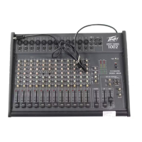
DDeessccrriippttiioonn
The UMA 752 is a high quality,
commercial grade analog audio
mixer/amplifier. Designed for flexibility in
application, this mixer/amp represent the
latest, state-of-the-art technology in
analog circuit design.
Powerful, yet easy to use, the new UMA
752 delivers amazing sonic performance.
Low-noise design and features applicable
to “real-world” situations makes this unit
ideal for audio applications where a
compact, powered mixer with multiple
input and output capabilities are
required.
AArrcchhiitteeccttuurraall aanndd EEnnggiinneeeerriinngg
SSppeecciiffiiccaattiioonnss
The mixer/amplifier shall have 4-inputs and
an accessory module port for use with
present and future Peavey MMA modules.
The front panel shall include four input
level controls, bass and treble controls, and
a master output control. Front panel
indicators shall include power, signal
presence at the amplifier, channel signal
and mute condition, and SPS
™
. The mixer
amplifier shall have a hierarchical muting
function where the input module has the
highest priority followed by Channel 1.
Outputs shall include one direct and three
transformer-balanced. The power switch
shall be on the rear panel along with the
detachable IEC cord, fuse holder, and
accessory power outlet (120 V only).
There shall be four inputs with Euro-type
connectors on the rear panel and level
controls on the front panel. Channel 1 shall
also include an XLR connector and have a
bridging transformer input with switchable
input sensitivity between telephone paging
and microphone. When in the microphone
mode, 24 Volt phantom power shall be
applied to the Input 1. Channel 2 shall be
electronically balanced with a switchable
input sensitivity between mic and line
levels. When in the microphone mode, 24
Volt phantom power shall be applied to the
Input 2. Channels 3 and 4 shall be
electronically balanced line-level inputs
with Channel 4 including stereo RCA jacks.
Additionally, the output from Channel 4
input shall be made available via an
electronically balanced output with a Euro-
type connector and a separate level
control. The module port shall be capable
of controlling both mute buses. Depending
upon the module chosen, it can be set up
for master configuration. When the input
signal to an input module commands a
mute function, Channels 1-4 shall be
muted.
Only Channel 1 shall have a continuously
variable mute threshold control on the rear
panel. Setting this control fully clockwise
shall defeat the Channel 1 mute function.
The mute level threshold for Channel 1
shall be increased as the control is turned
clockwise. When the signal level in Channel
1 exceeds the mute threshold, Channels 2-4
shall be muted. Channels 1 and 2 shall
include a switch to defeat its muting
function. When the switch is out, the
channel shall be muted. When the switch is
in, the channel cannot be muted.
 Loading...