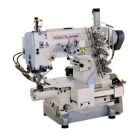
This document describes the Pegasus UT Device, a labor-saving thread trimmer designed for industrial sewing machines.
Function Description
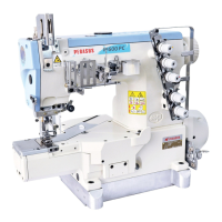
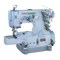
The Pegasus UT Device is designed to enhance efficiency in sewing operations by automating the thread trimming process. It is compatible with flatbed and interlock stitch machines and facilitates the easy trimming of needle, looper, and top cover threads by pressing the machine treadle with the heel. This eliminates the tedious manual thread trimming operation, significantly increasing productivity.
The device offers two types of driving methods for thread trimming and presser foot lifting: pneumatic and electric.
Important Technical Specifications
Models:
- W(T)200 Series
- W(T)600 Series
Electric Presser Foot Lift:
- Stroke A (standard): 28mm (Fig. 2)
Air Pressure Adjustment:
- Filter Regulator Setting: 0.5Mpa (5kgf/cm²) (Fig. 8)
Solenoid Assembly (Electric UT Device):
- Movement Amount: 17.9mm (with stopper 3) (Fig. 13)
- Crank 4 Installation Distance: 66.5mm from the left end of bracket 5 to the right end of crank 4 (solenoid not in operation) (Fig. 13)
- Connecting Rod 7 Distance: 36mm between the center of screw 8 and screw 9 (Fig. 13)
Air Cylinder (Pneumatic UT Device):
- Crank 12 Installation Distance: 100mm from the right end of bracket 13 to that of crank 12 (air cylinder not in operation) (Fig. 14)
- Connecting Rod 15 Distance: 36mm between the center of screw 16 and screw 17 (Fig. 14)
Lower Knife Adjustment:
- W600 Series (Left to Right): 65.5mm from the center of screws 2 to point A of the lower knife (Fig. 16)
- W200 Series (Left to Right): 65.5mm from the center of lower knife set screw 8 and tip A of the lower knife (Fig. 17)
- Front to Back: Lower knife 1 or 7 positioned 9mm past the right end of looper 9 and centered front to back over looper 9 (Fig. 17)
- Knife Holder Positioning (W600 Series): Knife holder guide 2 slightly contacts the end of lower knife holder 1 (Fig. 18)
- Knife Holder Positioning (W200 Series): Knife holder guide 5 slightly contacts the end of lower knife holder 4 (Fig. 18)
- Lower Knife Up and Down (W600/W200 Series): Bottom surface of lower knife 7 slightly contacts the top surface of looper 8 (Fig. 19)
- Extreme Left End of Travel: Point A of lower knife 1 positioned 22mm from the center of the needle bar (Fig. 20)
- Clearance B (Lower Knife at Extreme Left): Approximately 2mm (Fig. 22)
- Clearance C (Lower Knife Holder to Arm Bed): Approximately 1mm (Fig. 22)
Upper Knife Adjustment:
- Overlap: 0.5mm when the lower knife is at its farthest position to the right (Fig. 23)
Lower Knife Clamp Spring Adjustment:
- Position: 2mm to the right from the tip of the upper knife (Fig. 24)
Under Thread Holder Adjustment:
- Position: 2mm to the left from the tip of the upper knife (Fig. 25)
Upper Knife Stopper Adjustment:
- Clearance: 7-7.5mm between knife holder guide 2 and upper knife stopper 1 (Fig. 26)
Electric Needle Thread Wiper Adjustment:
- Clearance (Bracket 1 to Ring 4): 0-0.3mm (Fig. 29)
- Distance A: 10mm (Fig. 29)
- Distance B: 2mm (Fig. 29)
- Distance (Thread Wiper 8 to Needle Bar Center): Approximately 19mm (Fig. 29)
- Clearance (Thread Wiper 8 to Left Needle): Approximately 0.7mm (Fig. 29)
Pneumatic Needle Thread Wiper (Air Wiper) Adjustment:
- Opening 'a' Position: 1-2mm below the eye of the left needle (when needle is at highest position) (Fig. 32)
- Distance A (Air Wiper to Left Needle): 0.5-1.5mm (Fig. 32)
- Blowing Angle B: 0-5° (Fig. 32)
Pneumatic Top Cover Thread Trimmer Adjustment:
- Hook 1 Position: Above top cover thread 2 (when hook 1 protrudes) (Fig. 33)
- Clearance (Hook 1, Spreader 4, Left Needle 5): 0-0.5mm (Fig. 34)
Thread Releaser Adjustment:
- Clearance (Thread Tension Disks to Fingers): 0.2-0.5mm (Fig. 35)
- Distance A (Shaft 4): 30mm (Fig. 36)
- Releasing Amount (Cotton Threads): B=6mm, C=7mm, D=8.5mm, E=6.5mm, F=9mm (Fig. 36)
- With Top Cover Thread Trimmer (G): 15mm (Fig. 36)
Operation Detector Adjustment:
- Clearance (Operation Detector 10 to Magnet 11): 0.5mm (Fig. 37)
Usage Features
Easy Operation:
- Presser Foot Lift: The presser foot is raised by pressing the treadle with the heel.
- Sewing Start: The machine starts by pressing the treadle with the toe.
- Speed Adjustment: Machine speed can be freely adjusted by the amount of pressure applied to the treadle with the toe.
- Thread Trimming & Presser Foot Lift: The UT device actuates and lifts the presser foot when the treadle is pressed with the heel again after sewing, allowing for easy removal of fabric.
- Presser Foot Lift Knee Switch (Optional): Allows lifting the presser foot without trimming threads during sewing.
Threading:
- Looper Thread Take-up: For W600 models, a push button (1) allows lifting the looper thread take-up (2) for easier threading. For W200 models, the looper thread take-up can be lifted directly.
Air Line Connection:
- Secure Connections: Air lines must be inserted completely into joints and fastened securely to prevent damage or malfunction.
- Air Tube Removal: To remove an air tube, push the release ring toward the joint and pull out the air tube.
Speed Controller Adjustment:
- Separate Controls: Speed controllers (5 and 4) allow independent adjustment of the speed at which upper and lower knives protrude and retract.
- Fine-tuning: Loosen nut (6) and turn knob (7) counter-clockwise to increase speed, and clockwise to decrease speed.
Maintenance Features
Safety Precautions:
- Power Disconnection: Always turn off the power, unplug the machine, and shut down the air compressor before performing any maintenance, checks, adjustments, or repairs.
- Qualified Technicians: Installation and adjustments should only be performed by well-qualified technicians.
- Safety Covers: Ensure all safety covers and guards are properly secured and never removed during operation.
- Knife Edges: Exercise extreme caution around knife edges to prevent injury.
- Air Line Protection: Protect air lines from excessive force, bending, and damage (e.g., from staples).
- Grounding: Ensure all ground wires are securely connected to the ground terminal and indicated ground points on the machine head.
- Regular Checks: Before operation, check the machine head, unit, and device for any damage or defects. Repair or replace defective parts immediately.
- Foreign Matter: Prevent water, liquids, or metals from entering the device.
- Cleanliness: Regularly clean lint and other foreign matter from the device to prevent trouble.
- Periodic Drainage: For pneumatic devices, periodically drain and clean the filter regulator to prevent drainage from flowing into the solenoid valve or air cylinder.
Repair and Parts:
- Genuine Parts: Use only Pegasus' genuine parts for repairs and replacements.
- Unauthorized Modifications: Do not modify the device yourself. Pegasus disclaims responsibility for accidents caused by improper repair, adjustment, or unauthorized modifications.
Post-Maintenance Checks:
- Functionality Test: After any maintenance, checking, or repair, always ensure that no trouble occurs when the power is turned on.