Termoregolatore elettronico / Electronic thermostat
Manuale d’uso e manutenzione / Use and maintenance manual
Manuale d’uso e manutenzione / Use and maintenance manual
PEGO S.r.l.
Via Piacentina, 6/b - 45030 - ROVIGO
Tel : +39(0)425 762906 - Fax: +39(0)425 762905
www.pego.it - e-mail: info@pego.it
200NAN2ZN_01-12_ITA_ENG # Rev.01-12 # 26/01/2012
Manuale d’uso e manutenzione / Use and maintenance manual
DESCRIPTION
The Expert NANO 2ZN is an electronic regulator with two relays
for hot or cold in neutral zone. It can be used also for a double
setpoint with two separated outputs. It has one analogue input
for NTC temperature probe, two relays with separate contacts
and RS485 output for monitoring system (TeleNet or Modbus-
RTU). Buzzer is included and the power supply is 12V.
PRINCIPAL CHARACTERISTICS
Configurable for hot/cold call in neutral zone or as double set-
point with distinct outputs.
Key operated ON/OFF.
Display/adjustment of temperature with decimal point.
Flat front surface for easy cleaning and keys of ample dimensions
which can be customised with various colours (on request).
Internal buzzer for acoustic signals.
High brightness display with increased icons and figures.
PEGO programming philosophy guaranteeing immediate start-up.
RS485 serial connection with Modbus-RTU or Telenet protocol.
IP65 front protection. Two-fold fastening option: clips / screws.
Power supply 12V.
NANO2ZN SERIES MODELS
Power 12Vac/ac, 2 relays (8A+16A), hot/cold
function ,RS485, Buzzer, fixed clamps.
COMBINED ACTIVATION OF KEYS AND THEIR FUNCTIONS
FUNCTION / KEY COMBINATION
SETTINGS PROGRAMMING / (Set + o )
Press the SET key to view the current SETPOINT 1 value
(temperature).
Re-press the “Set” key down within 5 seconds from its leaving
for the visualization of the current SETPOINT 2 value
(temperature).
Keeping the SET key down and pressing either the () or ()
key, the selected SETPOINT value can be changed.
Release the SET key to return to view the room temperature;
the changes made will be automatically saved.
LEVEL 1 PROGRAMMING / ( + )
Press the UP and DOWN keys simultaneously for over 3 sec. to
access the Level 1 programming menu. When the menu is
accessed, a BIP is generated to confirm (if active). The system
leaves the menu after 30 seconds.
LEVEL 2 PROGRAMMING/ (++Stand-by)
Press the UP, DOWN and STAND-BY keys simultaneously for
over 3 sec. to access the Level 2 programming menu. When the
menu is accessed, a BIP is generated to confirm (if active) and
the system is placed in Stand-By mode.
EXIT PROGRAMMING MENUS / ( + )
Pressing the UP and DOWN buttons simultaneously in any
programming menu for over 3 sec. causes the system to save
the settings entered and leave that menu. A BIP is generated to
confirm (if active).
12V
~
+10/-15% 50/60Hz / 12Vdc +10/-15% class 2
-5T55°C - humidity < 90% Rel. Hum. Not condensing
-20T70°C - humidity < 90% Rel. Hum. Not condensing
Unsuitable operating
environments
Environments with strong vibrations or impacts; aggressive,
polluted or corrosive atmospheres, exposure to direct solar
radiation, explosive atmospheres or flammable gas.
3-Digit with sign, decimal point and LED status indicators
Probe precision (electronic)
Power clamps: fixed, screw for cables with c/section 0.2 to 2.5mm
2
Software class: A / Parameters saved on non-volatile memory (EEPROM)
1 Input for NTC probes (10K Ώ 1% at 25°C)
Dimensional, insulation and mechanical characteristics
93x37x65mm Depth 59mm
(Depth 69mm with removable clamps)
IP65 with front board installation
In front of board by means of rear fastening clips or or two front
screws
Plastic PC+ABS UL94 V-0 body, PC transparent front, Key panel PC
or PC+ABS
Conformity with EEC low voltage directives, electromagnetic compatibility and EC mark
Conforms to following EEC Directives : Directives 2004/108/EEC , 2006/95/EEC, 93/68 EEC
Conforms to following harmonised standards: EN60730-1, EN60730-2-9, EN61000-6-1, EN61000-6-3
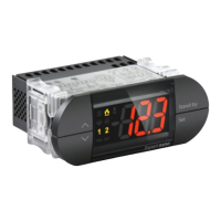
COLD FUNCTION ICON
(icon activated with mOd=0-1-2)
Led OFF = Cold function OFF
Led ON = Cold function ON
Flashing Led = Cold function ON waiting for C1 delay
(with mOD=0)
HOT FUNCTION ICON
(icon activated with mOd=0-1-3)
Led OFF = Hot function OFF
Led ON = Hot function ON
Flashing Led = Hot function ON waiting for C1 delay
(with mOD=0)
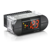
SET 1 ICON
(icon activated with mOd=2 or 3)
Led OFF = Hot/Cold function connected with set 1
OFF
Led ON = Hot/Cold function connected with set 1 ON
Flashing Led = Hot/Cold function connected with set
1 ON waiting for C1 delay
SET 2 ICON
(icon activated with mOd=1 or 2)
Led OFF = Hot/Cold function connected with set 2
OFF
Led ON = Hot/Cold function connected with set 2 ON
Flashing Led = Hot/Cold function connected with set
1 ON waiting for C1 delay
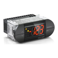
ALARM ICON
Led OFF = No alarm present
Led ON = Indicates temperature alarm intervention
with remedy.
Flashing Led = Alarm present
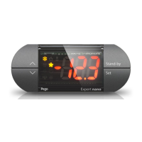
UP KEY
Increases values / Scrolls parameters in ascending
order / Deactivates acoustic alarm if present /
Acknowledges an alarm.
DOWN KEY
Decreases values / Scrolls parameters in descending
order.
STAND-BY KEY
If pressed for over 1 sec. alternates the Stand-By with
normal mode and vice versa. When mode is
alternated a BIP is generated to confirm. In Stand-By
mode the system stops and the display signals OFF
and the temperature alternating.
SET KEY
Displays the set point 1 and 2 (if active).
Allows the set point 1 and 2 to be entered when
pressed in combination with the DOWN or UP keys.
Resets the acoustic alarm if present.
FASTENING TO PANEL BY MEANS OF TWO BACK CLIPS
FASTENING TO PANEL BY MEANS OF TWO FRONT SCREW
GENERAL INFORMATION
PEGO S.r.l. does not accept responsibility for any loss of data or
information, costs of goods or substitute services, damages to
objects, persons or animals, lost sales or profits, interruption of
activities, any direct, indirect, accidental, property, insured, punitive,
special or consequential damage caused in any way, be it contractual,
extra-contractual or due to negligence or other responsibility
resulting from the use of the product or its installation. The guarantee
automatically becomes invalid in the case of poor functioning due to
tampering, impact or inadequate installation. It is mandatory to
observe all instructions in this manual and the operating conditions of
the device. PEGO S.r.l. does not accept responsibility for any
inaccuracies which may be present in this manual in the case that
these are due to printing or transcription errors and reserves the right
to make modifications to its products which it deems necessary or
appropriate, without prejudicing the products essential
characteristics.
ELECTRICAL PRESCRIPTIONS
Avoid using multipolar cables with conductors connected to inductive
and power loads and signal conductors such as probes and digital
inputs. Avoid installing in the same channels power cables and signal
cables (probes, digital inputs or RS485 connections). Reduce to a
minimum the length of the connecting cables, avoiding that the
cabling takes on a spiral form which may have inductive effects on
the electronic system. All conductors used in the cabling must be
appropriately sized in order to support the load which they must
provide. If it is necessary to extend the probes, use conductors with
appropriate cross-sections and not less than 1 mm². The extension or
reduction of the probes may alter the calibration which was
performed in the factory. Therefore, verify and calibrate by means of
an external thermometer.
Distance between hole
centres : 77mm
 Loading...