See Page 9 for Installation Data and pate 11 for Repair Parts
INSTALLATION INSTRUCTIONS
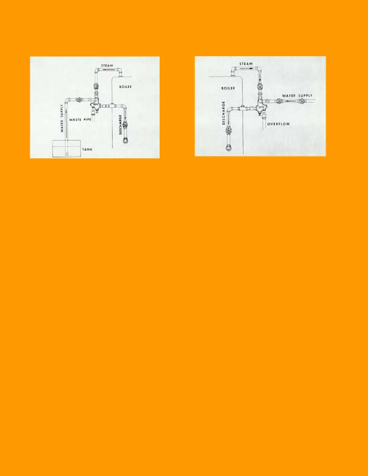
FOR SUCTION LIFT FOR WATER PRESSURE SUPPLY
Penberthy Injectors are used with any t ype of water supply.
To obtain the best possible results the following points should
be considered.
1. The steam pipe should be an independent line, the same
size as the injector connection and connected to the
boiler at the highest possible point.
2. If injector operates on a suction lift, the water supply pipe
should be one size larger than the injector connection ex-
cept on very short lifts. On long suction lifts, a pipe 2 sizes
larger with a f oot valve installed at end of pope i s recom-
mended. A glove valve, the full size of supply pipe, should
be installed in this line and the strainer which is provided
each injector should be attached at the end. It is very im-
portant tha the water supply pipe connection including the
valve stem packing be free from leaks.
Penberthy Injectors are used with any t ype of water supply.
To obtain the best possible results the following points should
be considered.
3. If injector water supply is taken from city water mains or an
overhead tank, better regulation of water may be obtained
if two globe valves are i nstalled in the water supply line.
The valve nearest the injector is used to regulate the wa-
ter supply while the second valve is adjusted permanently
to provide the most desirable pressure reduction.
4. The delivery pipe should be the same size as the injector
connection or larger if desired. A swing check valve and a
globe valve should be installed in this line, which should be
as direct and as f ree from elbows as the installation will
permit.
OPERATION
To Start:
Fully open the water supply valve and the discharge
valve. Next, fully open the steam valve. If water continues to
come out of overflow connection, throttle the water supply
valve until is stops. On low pressure operation it may be nec-
essary to throttle the water supply valve in order t o establish
injector operation. On high pressure operation it is satisfactory
to throttle the steam valve until the water supply pipe is
rimed
but under all other conditions the steam valve should
be wide open and regul ation of flow governed by the water
supply valve.
To Stop:
Close the steam valve. The water supply valve
need not be closed unless supply water is under pre ssure.
The discharge line valve needs to be closed only as a precau-
tionary measure as the check valve will prevent back flow from
the boiler.
9
NORTHEAST CONTROLS INCORPORATED
TEL: 201-419-6111 ext. 23 for Venturi Group
NORTHEAST CONTROLS INCORPORATED
TEL: 201-419-6111 ext. 23 for Venturi Group
 Loading...