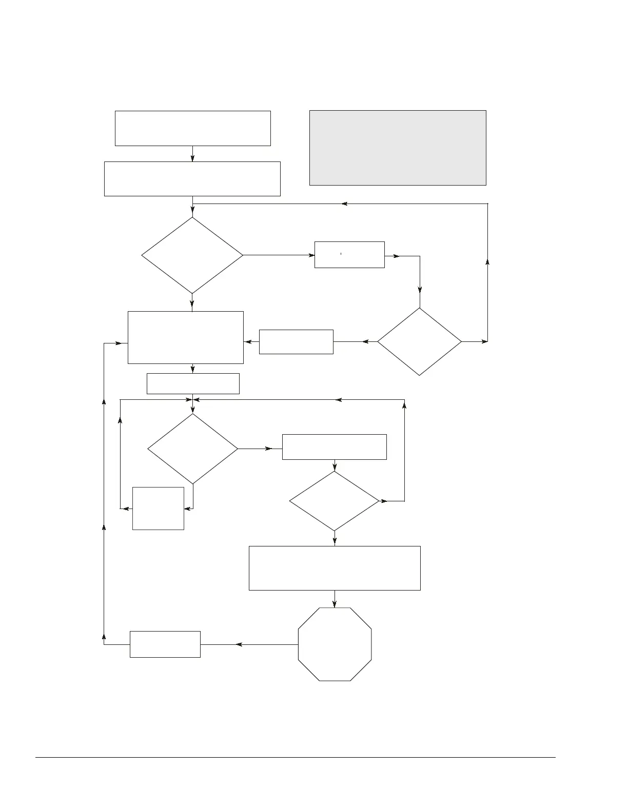
Power to the refrigeration control
system is interrupted and the
anti-short cycling timer starts.
Operating control energizes the P545 control,
and if time other than zero is selected, the
anti-short cycle timer continues to time out.
Has anti-short
cycle delay
time elapsed?
No
No
No
No
Yes
Yes
Yes
Yes
Do you want
short cycle
to continue?
Yellow LED On
Compressor contacts close;
LLS contacts remain closed
and alarm remains open;
green LED On;
yellow LED On.
Is the net
lube oil pressure
sufficient?
Timer
counts down;
yellow
LED Off.
Green and yellow LEDs On
time delay counts up.
Has lube
delay timeout
limit been
reached?
Alarm contacts close;
compressor contacts and
liquid line solenoid contacts open;
red LED On, yellow and green LEDs Off.
Correct
lubrication problem
and press the
Reset button.
Red LED Off;
alarms clear.
Low lube oil pressure
time delay initiated.
Compressor Contacts: M1 to M2
Alarm Contacts: CMA to NOA
Liquid Line Solenoid Contacts: CMA to NCA
Note:
.
Push Reset button.
;
1201102_2.cdr
 Loading...