6 P545 Series Electronic Lube Oil Control Product/Technical Bulletin
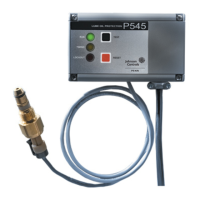
Internal Wiring Diagram
M1
M2
L2
120
240
P545
NCANOA
CMA
Factory-Mounted
External Metal Jumper
Do not connect circuit interrupts here.
Circuit interrupts are permitted here
.
12011012_7.cdr
Figure 7: Internal Wiring Diagram for the P545 Control
Ladder Diagrams for the P545 Control
M1
M2
L2
120
240
P545
NCANOA
CMA
L1
L2
L3
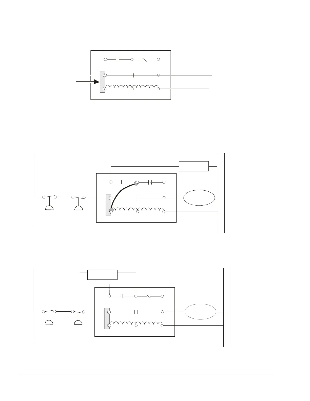
Compressor
Contactor
Wire Jumper
Low
Pressure
Control
High
Pressure
Control
Alarm
Connection
12
011
012_
8.c
dr
Figure 8: Typical P545 Control Application with Alarm Circuit Powered by Line Voltage
Low
Pressure
Control
High
Pressure
Control
M1
M2
L2
120
240
P545
NCA
NOA
CMA
L1
L2 L3
Compressor
Contactor
Alarm
Connection
Power
for Alarm
Circuit
12011012_9.cdr
Figure 9: Typical P545 Control Wiring with Alarm Circuit Powered by a Separate Voltage
 Loading...