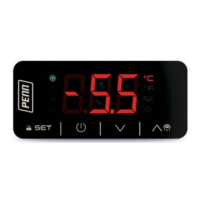
PENN | TC3B23 | Installation Guide Rev. B | Part No. 24-7664-03574 | Page 1 of 2 | 07 April 2020
TC3B23
Basic controller for refrigerated cabinets,
with energy-saving strategies
E ENGLISH
- Controller for low temperature units.
- Power supply for TC3B23N5V: 115 VAC.
- Power supply for TC3B23N7V: 230 VAC.
- Cabinet probe and auxiliary probe (NTC).
- Door switch/multi-purpose input.
- Cooling or heating operation.
1 MEASUREMENTS AND INSTALLATION
Measurements in mm (inches). To be fitted to a panel, snap-in brackets provided.
INSTALLATION PRECAUTIONS
- The thickness of the panel must be between 0.8 and 2.0 mm (1/32 and 1/16 in)
- Ensure that the working conditions are within the limits stated in the TECHNICAL
SPECIFICATIONS section.
- Do not install the device close to heat sources, equipment with a strong magnetic field,
in places subject to direct sunlight, rain, damp, excessive dust, mechanical vibrations
or shocks.
- In compliance with safety regulations, the device must be installed properly to ensure
adequate protection from contact with electrical parts. All protective parts must be
fixed in such a way as to need the aid of a tool to remove them.
2 ELECTRICAL CONNECTION
Important
- Use cables of an adequate wire gauge for the current running through them.
- To reduce any electromagnetic interference connect the power cables as far away
as possible from the signal cables.
-
Power supply for TC3B23N5V: 115 VAC.
- Power supply for TC3B23N7V: 230 VAC.
PRECAUTIONS FOR ELECTRICAL CONNECTION
- If you use an electrical or pneumatic screwdriver, adjust the torque to a maximum of
0.5 N•m (4 in. lb).
- If the device was moved from a cold to a warm place, the humidity may have caused
condensation to form inside. Wait about an hour before switching on the power.
- Make sure that the supply voltage, electrical frequency and power are within the set
limits. See the section TECHNICAL SPECIFICATIONS.
- Disconnect the power supply before doing any type of maintenance.
- Do not use the device as safety device.
- For repairs and for further information, contact the PENN sales network.
3 FIRST-TIME
1. Install following the instructions given in the section MEASUREMENTS AND INSTALLA-
TION.
2. Power up the device as shown in the section ELECTRICAL CONNECTION and an internal
test will be run.
The test normally takes a few seconds, when it is finished the display will switch off.
3. Configure the device as shown in Table 6.1 in the section SETTINGS.
Recommended configuration parameters for first-time use.
PAR. DEF. PARAMETER MIN... MAX.
SP 0.0 setpoint r1... r2
P2 0 temperature unit of measurement 0 = °C 1 = °F
d1 0 defrost type 0 = electric 1 = hot gas
2 = compressor stopped
Then check that the remaining settings are appropriate; see the section CONFIGURA-
TION PARAMETERS.
4. Disconnect the device from the mains.
5. Make the electrical connection as shown in the section ELECTRICAL CONNECTION with-
out powering up the device.
6. Power up the device.
4 USER INTERFACE AND MAIN FUNCTIONS
4.1 Switching the device on/off
1. If POF = 1, touch the ON/STAND-BY key for 4 s.
If the device is switched on, the display will show the P5 value ("cabinet temperature" default);
if the display shows an alarm code, see the section ALARMS.
LED ON OFF FLASHING
com
pressor on compressor off - compressor protection active
- setpoint setting active
de
frost or pre-dripping
active
- - defrost delay active
- d
ripping active
evaporator fan on evaporator fan off
evaporator fan stop active
-
if device on, energy
saving active
- if device off, low
consumption active
- -
°C/°F
view temperature - -
de
vice off device on device on/off active
I
f 30 s have elapsed without the keys being pressed, the display will show the “Loc” label and
the keypad will lock automatically.
4.2 Unlock keypad
Touch any key for 1 s: the display will show the label “UnL”.
4.3 Set the setpoint
Check that the keypad is not locked.
1. Touch the SET key.
2.
Touch the UP or DOWN key within 15 s to set the value within
the limits r1 and r2 (default “-40... 50”)
3. Touch the SET key (or do not operate for 15 s).
4
.4 Activate manual defrost (if r5 = 0, default)
Check that the keypad is not locked.
1. Touch the UP key for 2 s.
If P4 = 1 (default), defrost is activated provided that the evaporator temperature is lower than
the d2 threshold.
5 ADDITIONAL FUNCTIONS
5.1 View/delete compressor functioning hours
Check that the keypad is not locked.
1. Touch the DOWN key for 4 s.
2. Touch the UP or DOWN key within 15 s to select a label.
LAB. DESCRIPTION
CH view compressor functioning hours (hundreds)
rCH delete compressor functioning hours
3. Touch the SET key.
4.
Touch the UP or DOWN key to set “149” (when label “rCH” is se-
lected).
5. Touch the SET key.
6.
Touch the ON/STAND-BY key (or do not operate for 60 s) to exit
the procedure.
5.2
View the temperature detected by the probes
Check that the keypad is not locked.
1. Touch the DOWN key for 4 s.
2. Touch the UP or DOWN key within 15 s to select a label.
LAB. DESCRIPTION
Pb1 cabinet temperature
Pb2 auxiliary temperature
3. Touch the SET key.
4.
Touch the ON/STAND-BY key (or do not operate for 60 s) to exit
the procedure.
6 SETTINGS
6.1 Setting configuration parameters
1. Touch the SET key for 4 s: the display will show the label “PA”.
2. Touch the SET key.
3.
Touch the UP or DOWN key within 15 s to set the PAS value (de-
fault “-19”).
4.
Touch the SET key (or do not operate for 15 s): the display will
show the label “SP”.
5. Touch the UP or DOWN key to select a parameter.
6. Touch the SET key.
7. Touch the UP or DOWN key within 15 s to set the value.
8. Touch the SET key (or do not operate for 15 s).
9.
Touch the SET key for 4 s (or do not operate for 60 s) to exit the
procedure.
6
.2 Restore the factory settings (default) and store customized settings as default
Important
- Check that the factory settings are appropriate; see the section CONFIGURATION
PARAMETERS.
- When you store customized settings, you overwrite the default.
1.
Touch the SET key for 4 s: the display will show the label “PA”.
2. Touch the SET key.
3. Touch the UP or DOWN key within 15 s to set the value.
VAL. DESCRIPTION
149 value to restore the factory settings (default)
161 value to store customized settings as default
4.
Touch the SET key (or do not operate for 15 s): the display will
show the label “dEF” (when value “149” is set) or the label
“MAP” (when value “161” is set).
5. Touch the SET key.
6. Touch the UP or DOWN key within 15 s to set “4”.
7.
Touch the SET key (or do not operate for 15 s): the display will
show for 4 s “- - -“ flashing, then the device will exit the proce-
dure.
8. Interrupt the power supply to the device.
9.
Touch the SET key 2 s before action 6. to exit the procedure be-
forehand.
7 CONFIGURATION PARAMETERS
N. PAR. DEF. SETPOINT MIN... MAX.
1 SP 0.0 setpoint r1... r2
N. PAR. DEF. ANALOG INPUTS MIN... MAX.
2 CA1 0.0 cabinet probe offset -25... 25 °F/°C
3 CA2 0.0 auxiliary probe offset -25... 25 °F/°C
4 P0 1 probe type 0 = n/a 1 = NTC
5 P1 1 enable °C decimal point 0 = no 1 = yes
6 P2 0 temperature unit of
measurement
0 = °C 1 = °F
7 P4 1 auxiliary probe function 0 = disabled
1 = evaporator probe (de-
frost + fan)
2 = evaporator probe (fan)
3 = condenser probe
8 P5 0 value displayed 0 = cabinet temperature
1 = setpoint
2 = auxiliary temperature
9 P8 5 display refresh time 0... 250 s : 10
N. PAR. DEF. CONTROL MIN... MAX.
10 r0 2.0 setpoint differential 1... 15 °F/°C
11 r1 -40 minimum setpoint -99 °F/°C... r2
12 r2 50.0 maximum setpoint r1... 199 °F/°C
13 r4 0.0 setpoint offset in energy saving 0... 99 °F/°C
14 r5 0 cooling or heating operation 0 = cooling
1 = heating
15 r12 1 position of the r0 differential 0 = asymmetric
1 = symmetric
N. PAR. DEF. COMPRESSOR MIN... MAX.
16 C0 0 compressor on delay after pow-
er-on
0... 240 min
17 C2 3 compressor off minimum time 0... 240 min
18 C3 0 compressor on minimum time 0... 240 s
19 C4 0 compressor off time during cabi-
net probe alarm
0... 240 min
20 C5 10 compressor on time during cabi-
net probe alarm
0... 240 min
21 C6 80.0 threshold for high condenser
temperature warning
0... 199 °F/°C
differential = 4 °F/2 °C
22 C7 90.0 threshold for high condenser
temperature alarm
0... 199 °F/°C
23 C8 1
high condenser temperature
alarm delay
0... 15 min
N. PAR. DEF. DEFROST (if r5 = 0) MIN... MAX.
24 d0 8 automatic defrost interval 0... 99 h
0 = only manual
if d8 = 3, maximum interval
25 d1 0 defrost type 0 = electric
1 = hot gas
2 = compressor stopped
26 d2 2.0 threshold for defrost end -99... 99 °F/°C
27 d3 30 defrost duration 0... 99 min
if P3 = 1, maximum duration
28 d4 0 enable defrost at power-on 0 = no 1 = yes
29 d5 0 defrost delay after power-on 0... 99 min
30 d6 1 value displayed during defrost 0 = cabinet temperature
1 = display locked
2 = dEF label
31 d7 2 dripping time 0... 15 min
32 d8 0 defrost interval counting mode 0 = device on hours
1 = compressor on hours
2 = hours evaporator tem-
perature < d9
3 = adaptive
33 d9 0.0 evaporation threshold for auto-
matic defrost interval counting
-99... 99 °F/°C
34 d11 0 enable defrost timeout alarm 0 = no 1 = yes
35 d15 0 compressor on consecutive time
for hot gas defrost
0... 99 min
36 d18 40 adaptive defrost interval 0... 999 min
if compressor on + evapora-
tor temperature < d22
0 = only manual
37 d19 3.0 threshold for adaptive defrost
(relative to optimal evaporation
temperature)
0... 40 °F/°C
optimal evaporation tempera-
ture - d19
38 d20 180 compressor on consecutive time
for defrost
0... 999 min
0 = disabled
39 d22 2.0 evaporation threshold for adap-
tive defrost interval counting
(relative to optimal evaporation
temperature)
0... 19 °F/°C
optimal evaporation tempera-
ture + d22
N. PAR. DEF. ALARMS MIN... MAX.
40 A1 10.0 threshold for low temperature
alarm (relative to setpoint)
0... 99 °F/°C
SP - A1
0 = disabled
41 A4 10.0 threshold for high temperature
alarm (relative to setpoint)
0... 99 °F/°C
SP + A4
0 = disabled
42 A6 12 high temperature alarm delay af-
ter power-on
0... 99 min x 10
43 A7 15 high/low temperature alarms de-
lay
0... 240 min
44 A8 15 high temperature alarm delay af-
ter defrost
0... 240 min
45 A9 15 high temperature alarm delay af-
ter door closing
0... 240 min
46 A11 2.0 high/low temperature alarms re-
set differential
1... 15 °F/°C
N. PAR. DEF. FANS MIN... MAX.
47 F0 3 evaporator fan mode during
normal operation
0 = off 1 = on
2 = on if compressor on
3 = thermoregulated (with
F1)
4 = thermoregulated (with
F1) if compressor on
48 F1 -1.0 threshold for evaporator fan op-
eration
-99... 99 °F/°C
differential = 2 °F/1 °C
49 F2 0 evaporator fan mode during de-
frost and dripping
0 = off 1 = on
2 = according to F0
50 F3 2 evaporator fan off maximum
time
0... 15 min
51 F4 30 evaporator fan off time during
energy saving
0... 240 s x 10
52 F5 30 evaporator fan on time during
energy saving
0... 240 s x 10