13
www.PennBarry.com
WIRING HARNESS – ECM
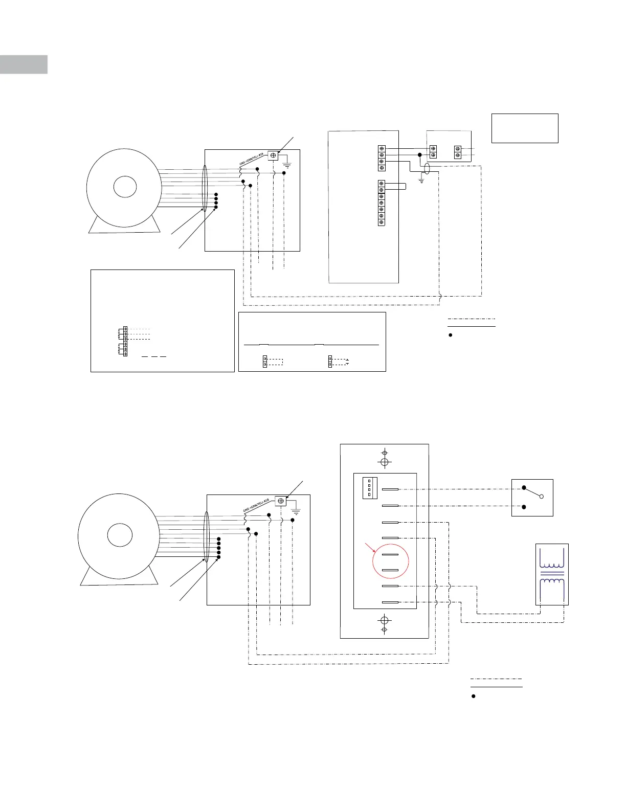
3) T.E. Motors 120v/240v/460v Single Phase (with iQ-IPCM controller)
4) T.E. Motors 120v/240v/460v Single Phase (with iQ-MS controller)
This drawing illustrates our understanding of order requirements. When approved, it represents details for fabrication, as such,
PennBarry will not be responsible for revisions in the eld or other changes after release for fabrication. Published and protected by
PennBarry, Plano, TX. All rights reserved. May not be reproduced partially or in full without permission from the publisher. No rights
conveyed to manufacture partially or in full, use or sell either the method of construction represented or any invention in any way
related thereto.
EXC
COM
VOUT
mA
D l 1
D_COM
D l 2
AN1
A_ COM
AN2
A_ COM
Terminal Block 1
Terminal Block 2
+( 24VDC )
- ( Common )
Power
Supply
24 VDC Power Supply
L1 <BLK> #18
L2/N <RED> #18
GND <GRN/YEL> #18
COMMON <BLUE> #18
ANALOG IN <BRN> #18
PRGR#2 <WHT> #18
PRGR#3 <YEL> #18
PRGR#4 <ORG> #18
PRGR#5 <PRP> #18
COM
+10VDC
L1
GND
L2N
COMMON<BLUE> #18
ANALOG IN <BRN> #18
L1 <BLK> #18
L2/N <RED> #18
JUNCTION BOX
WIRE CLAMP
CONNECTIONS TERMINATED
AND FOR FACTORY USE ONLY
Enable Jumper
Low Voltage 0-10
VDC, 2 x 18 AWG,
<300 Shielded
Analog Speed Signal
to EC Motor or VFD
Oponal Status Connecons
The relays will energize when all of the following condions are met:
1. The IPCM is energized
2. The corresponding input is enabled
3. The system pressure is within the high and low pressure limits
Figure 9: Example Terminal Block #3 wiring connecons when DI1 input
is used and RLY1 output is use to drive external device/appliance
DI1 = RELAY 1
DI2 = RELAY 2
Terminal Block 3
RUNNING / NORMAL OUTPUT
EXTERNAL SIGNAL INPUT
DISABLED / ALARM OUTPUT
Field Wired
RLY 1 NO
RLY 1 COM
RLY 1 NC
RLY 2 NO
RLY 2 COM
RLY 2 NC
GROUNDING BLOCK
FIELD WIRED, BY OTHERS
FACTORY WIRED
WIRED CONNECTION
**Note, Power Supply IN can be
selected as 24VAC, 115/230VAC (Low
Voltage), or 277/460VAC (High
Voltage – Single Phase only). Power
Supply can also be, “by others.”
Oponal Enable Connecons
A B
IPCM IPCM
Terminal Block 2
DI1 (Enable #1)
Install jumper
for connuous
operaon
Install dry contact or
switch to enable disable
IPCM
D_COM
DI1 (Enable #1)
D_COM
Terminal Block 2
The majority of IPCM systmes run in a connuous modulang mode of operaon with
DI1 jumped to D_COM on terminal block #2. See illustraon A below. When the ability
to enable and disable the system is desired, a dry contact or switch will need to be
wired between DI1 and D_COM. Refer to illustraon B below.
The IPCM has two dry SPDT relay contacts for status output. Each relay
corresponds to a digital input. Relay 1 is acve when DI1 is enabled and relay 2 is
acve when DI2 is enabled.
TRANSFORMER PROVIDED
BY OTHERS.
ANALOG CONNECT TO EC
MOTOR 0-10VDC
OPTIONAL
24VAC OUTPUT
HI-LO
COMMON
24VAC
COMMON
NEUTRAL
MOTOR
SWITCH PROVIDED
BY OTHERS
L1 <BLK> #18
L2/N <RED> #18
GND <GRN/YEL> #18
COMMON <BLUE> #18
ANALOG IN <BRN> #18
PRGR#1 <GREEN> #18
PRGR#2 <WHT> #18
PRGR#3 <YEL> #18
PRGR#4 <ORG> #18
PRGR#5 <PRP> #18
COM
+10VDC
L1
GND
L2N
COMMON <BLUE> #18
ANALOG IN <BRN> #18
L1 <BLK> #18
L2/N <RED> #18
JUNCTION BOX
WIRE CLAMP
CONNECTIONS TERMINATED
AND FOR FACTORY USE ONLY
GROUNDING BLOCK
FIELD WIRED, BY OTHERS
FACTORY WIRED
WIRED CONNECTION
24VAC
NEUTRAL
24VAC
LINE VOLTAGE
NO-SETPOINT 1
NC-SETPOINT 2
 Loading...