Do you have a question about the Pentair Pool Products PG2000 840240 and is the answer not in the manual?
Emphasizes the importance of reading and following all instructions before use.
Warns about electrical hazards during installation and use of the PG2000 unit.
Instructs users to retain the safety instructions for future reference.
Details electrical input voltage and power consumption for the PG2000 unit.
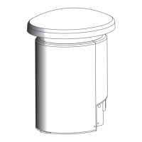
Provides mechanical specifications including dimensions, weight, and materials.
Lists all items expected to be found within the PG2000 product packaging.
Lists necessary electrical supplies, cable, fittings, kits, and tools for installation.
Presents ten essential laws for installers to follow for proper FIBERworks installation.
Crucial warning against attempting installation without proper training or video review.
Advises patience and correct technique during fiber termination to ensure quality.
Recommends direct conduit runs and specific elbow types to prevent fiber damage.
Instruction to avoid bending the final 12 inches of fiber optic cable before the lens.
Guidance on installing the sub-terrain mounting base relative to grade level.
Recommendation to position the PG2000 unit above water level to prevent flooding.
Details the steps for proper cable termination at the PG2000 unit.
Provides contact information for technical assistance when encountering doubts during installation.
Highlights the superior light and color quality of FIBERworks products.
Advises on customer service to encourage positive referrals and satisfaction.
Explains the trade-off between cable length, cost, and light transmission efficiency.
Emphasizes strategic placement of the PG2000 for optimal cable run lengths.
Advises against using fiber optics on dark pool surfaces due to light absorption.
Suggests dark pool surfaces enhance the visual impact of perimeter FIBERworks lighting.
Describes the illumination capabilities of FIBERworks lenses on target surfaces.
Introduces the availability of two types of underwater lenses for different applications.
Stresses the importance of using certified installers for optimal performance.
Provides contact details for technical service support when assistance is needed.
Offers design assistance via faxing a FIBERCAD form and scale drawing.
Advises keeping the PG2000 close to the pool to maximize light output.
Details positioning for Wide Angle lenses with specific AmerGlow models at the pool end.
Specific placement for Wide Angle lenses in light to medium colored pools.
Describes single and dual lens configurations for end wall placement.
Details positioning for specific AmerGlow models on the pool side.
Guidelines for lens placement to achieve uniform pool illumination.
Principle that lighting effectiveness is maximized when the lens faces the desired surface.
Specifies lens placement depth in concrete or fiberglass pools.
Provides depth-based positioning instructions for lenses in vinyl pools.
Table showing light transmission data for various AmerGlow cable sizes and lengths.
Explanation of how cable length impacts light transmission efficiency.
Warns about the necessity of adequate lighting to prevent swimming and diving hazards.
Provides essential tips for running conduit, including elbow types and pipe materials.
Suggests using electrician's lube to facilitate cable feeding through conduit.
Guides on selecting the appropriate conduit size based on AmerGlow cable type.
Details electrical conduit requirements for different PG2000 wiring configurations.
Emphasizes the critical importance of proper grounding for electrical safety.
Provides instructions for running conduit specifically for AmerGlow fiber optic cables.
Specifies minimum depth for conduit near the PG2000 when using a sub-terrain base.
Mandates the use of specific sweep elbows to prevent fiber damage.
Directs users to refer to previous sections for correct lens body placement.
Specifies a minimum straight conduit length required behind the lens housing.
Illustrates the specific cut-back dimensions for lens housing in gunite pools.
Notes that FIBERworks lens housings are installed similarly to standard water return fittings.
Warns against using non-FIBERworks housings as they may not seal conduit properly.
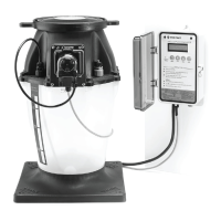
Presents two primary methods for mounting the PG2000 unit.
Describes mounting the PG2000 using the included sub-terrain mounting base.
Details mounting the PG2000 directly onto a flat surface without the base.
Guides on the installation process for the sub-terrain mounting base.
Method for securing the mounting base using angled rebar.
Specifies how to cut fiber and electrical conduit relative to the mounting base.
Details the process for mounting the unit onto wood decks or concrete surfaces.
Lists the necessary tools and materials for mounting on decks or concrete.
Lists the tools and materials needed for sub-terrain base and deck installations.
Shows conduits positioned according to the PG2000 template.
Instructions on cutting the sub-base flanges for proper fit.
Demonstrates securing the base by driving rebar at an angle into the corners.
Guidance on backfilling around the base for mulch or concrete.
Steps for securing the unit to a concrete deck using anchors.
Specifies cutting fiber optic conduits to a precise height above the deck.
Instructions for removing the PG2000 outer body for installation access.
Guidance on positioning the PG2000 subassembly over the conduit.
Steps for marking and drilling holes for anchors on concrete surfaces.
Instruction to temporarily set aside the PG2000 subassembly.
Lists the necessary tools and materials for feeding or pulling the AmerGlow cable.
Offers helpful tips and potential pitfalls to avoid when handling the AmerGlow cable.
Recommends using electrician's lube to ease the process of pulling cable through conduit.
Suggests creating a pilot tip with tape to aid in guiding the cable through conduit.
Details sealing the conduit at the PG2000 location to prevent debris and water entry.
Advises leaving sufficient cable length at the pool end for installation.
Specifies the required cable extension above the PG2000 mounting point for ease of installation.
Warns against bending the first 12 inches of factory-cut cable to prevent damage.
Stresses the importance of accurately measuring and accounting for required cable length.
Instructions for removing specific parts from lens housings for installation.
Reminds users to remove a reminder tag from the fiber optic cable.
Suggests using fish tape to pull the cable through the conduit if necessary.
Notes that a fish tape may not always be required for AmerGlow cable feeding.
Describes how to securely attach the cable to fish tape at the pool end.
Details the coordinated action required for pulling the cable using fish tape.
Instruction on when to stop feeding the cable, leaving a specific length on the pool side.
Ensures O-rings are correctly positioned and clean before assembly.
Guides the final pulling of the cable until the lens assembly is near its final position.
Warns against pulling the cable to seat the lens, which can impair termination.
Describes the process of placing the retaining nut and pushing the lens into position.
Details hand-tightening the lens using the specific tool until the O-ring seats.
Specific tightening instructions for standard lens housings.
Specific tightening instructions for Invisible Gunite and Vinyl Liner housings.
Instructions for pulling or feeding bulk AmerGlow cable.
Method for feeding fish tape through the conduit from the pool side.
Describes attaching the bulk cable to the fish tape securely.
Specifies the required cable extension at both the lens and PG2000 locations.
Lists the necessary tools and materials for assembling the AmerGlow lens.
Confirms the expected cable length protruding from the lens housing.
Warns users about the high temperatures of the FiberKnife and safe handling practices.
Instructions for plugging in and warming up the FiberKnife tool.
Recommends a waiting period between cuts for the FiberKnife to reheat.
Details using the stripping tool to remove cable jacket, referencing an image.
Warns against damaging fibers during stripping, which can reduce light output.
Suggests practicing stripping on spare cable to improve technique.
Explains how to adjust the cable stripper's cutting depth using the black knob.
Details the correct way to place the stripper on the cable using the spring guide.
Describes the rotation technique for the stripper using the black knob.
Advises checking the blade orientation if the stripper is not cutting correctly.
Instructions for completing jacket removal after initial stripping.
Recommends fanning the fiber ends to clear residual powder.
Details placing the spacer and O-ring for specific lens housing types.
Guides on assembling the seal nut, referencing a figure for details.
Instructions for sliding the compression nut onto the cable correctly.
Details selecting and positioning the grommet onto the cable.
Advises keeping the cable straight after it exits the lens housing.
Describes placing the seal nut and tightening the compression nut.
Lists the tools and materials needed for the AmerGlow lens assembly.
Instruction to remove 1 inch of cable jacket using the stripper.
Details adding tape, spacer, compression nut, and grommet to the cable.
Instructions for adding and tightening the seal nut.
Step to screw the cutting shield onto the assembly.
Guidance on holding the hot knife at a 15-degree angle.
Details filling the Standard Lens reservoir with OptiFusion gel.
Clarifies that gel is not needed for the Wide Angle Lens.
Describes the final step of screwing on the lens cap.
Shows cable placement in the fitting, with notes on using a spacer.
Instructions for hand-tightening the lens retainer nut.
Details the technique for tightening the compression nut while holding the seal nut.
Guidance on tightening the compression nut to the correct flush position.
Suggests pulling the assembly to verify the cable is securely held.
Diagram illustrating the components of the lens assembly and their order.
Highlights the critical nature of the fiber cutting step for successful installation.
Instructions for threading the cutting shield onto the seal nut.
Advises holding the cable straight at the seal nut during cutting.
Warns against excessive force with the FiberKnife, emphasizing heat usage.
Guides on applying consistent pressure and correct angle during the cutting process.
Advises easing pressure at the end of the cut to prevent fiber folding.
Warns that the cutting shield may be hot and advises caution during removal.
Guides on inspecting the cut fiber for smoothness and quality.
Defines the criteria for a proper, high-quality fiber cut.
Emphasizes the importance of a professional cut for system performance.
Lists common reasons that can lead to a poor fiber cut.
Advises on the replacement frequency for FiberKnife blades.
Procedures for installing the lens into the assembly.
Instruction to clean the fiber face before lens installation.
Details filling the Standard Lens reservoir with OptiFusion gel.
Clarifies that gel is not needed for the Wide Angle Lens.
Guides on assembling the lens to the seal nut.
Advises checking O-rings for cleanliness and proper placement.
Details tightening the lens onto the seal nut using a wrench.
Ensures correct placement and cleanliness of spacers and O-rings.
Instructions to clean the sealing surface of the lens housing.
Guides cable feeding until the lens assembly is near its final position.
Warns against improper seating of the lens housing by pulling the cable.
Describes placing the retaining nut and pushing the lens into its housing.
Details hand-tightening the lens with the tool until the O-ring seats.
Specific tightening procedure for standard lens housings.
Specific tightening procedure for Invisible Gunite/Vinyl Liner housings.
Offers a helpful tip for easier installation of FIBERworks components.
Notes a specific installation detail for vinyl liner pools regarding lens sealing.
Details the preparation and installation steps for the cable into the ferrule assembly.
Warns about the high temperatures of the FiberKnife and safe handling practices.
Specifies mechanically cutting all cables to a uniform length.
Details using the stripping tool to remove cable jacket from the base.
Guides on adjusting the stripper and practicing before actual use.
Advises checking blade orientation if the stripper is not cutting correctly.
Instructions for completing jacket removal after initial stripping.
Recommends fanning fiber ends to clear residual powder.
Details the process of loading the fiber optic cable into the ferrule.
Instructs on gathering and taping the stripped fiber ends.
Advises fanning fiber ends to clear powder from between them.
Suggests placing less critical fibers on the outer part of the bundle.
Recommends using a flashlight to help identify fibers during arrangement.
Guides on adding fibers to reach a specific count (100 or 200) if the initial amount is less.
Warns that fibers outside the 400 bundle diameter may reduce light output.
Instructs to select the correct compression nut and grommet based on fiber count.
Advises consulting Table 2 to determine the necessity of a ferrule insert.
Details the order and orientation for sliding components onto the fiber bundle.
Specifies the required fiber length protruding from the ferrule posts.
Guides on tightening the compression nut to secure the fibers in the ferrule.
Warns against using mounting flanges for leverage to avoid breakage.
Advises ensuring fibers are not twisted or tangled before tightening.
Suggests pulling the bundle to confirm secure fiber holding.
Offers a tip using electrical tape to improve the grommet's grip.
Instructions for installing the fiber disk onto the ferrule assembly.
Guides on selecting the appropriate fiber disk based on the fiber count.
Warns that only new metal fiber disks should be used with this unit.
Table mapping fiber ranges to the corresponding metal fiber disk part numbers.
Lists the tools and materials needed for ferrule assembly installation.
Instruction to cut all cables to a specific length above the base.
Details stripping cable jackets to a specified length above the base.
Guides on assembling the compression nut, grommet, and ferrule body.
Instructions for securely tightening the ferrule assembly.
Suggests pulling on the ferrule to verify tightness.
Guides on selecting the appropriate numbered fiber disk.
Instruction to snap the fiber disk into place.
Step to screw the cutting shield onto the ferrule assembly.
Details performing the hot knife cut at a specific blade angle.
Guides on inspecting the cut for quality, checking for lines or puddles.
Instruction to position the PG2000 unit without securing it yet.
Details tipping the PG2000 back and securing its "ears".
Instructions for securing the PG2000 unit to its base.
Guidance on carefully installing the outer body of the PG2000.
Details securing the outer body with the provided screws.
Instructions for snapping the fiber disk into its support posts.
Warns about ensuring sufficient cable slack for proper placement.
Details the fiber cutting process, referencing images on a previous page.
Instructions for threading the cutting shield onto the ferrule assembly.
Guides on holding the assembly straight during the cutting process.
Details positioning the FiberKnife blade at the correct angle against the shield.
Advises against rushing and recommends sufficient time for cutting larger fiber bundles.
Warns against excessive force and improper actions with the FiberKnife.
Advises easing pressure at the end of the cut to prevent fiber folding.
Instructions for removing the cutting shield and cleaning the fiber face.
Warns that the cutting shield may be hot and advises caution during removal.
Guides on inspecting the cut fiber for quality.
Defines the criteria for a proper fiber cut.
Emphasizes the importance of a professional cut for system performance.
Lists common reasons for a poor fiber cut.
Advises on the replacement frequency for FiberKnife blades.
Outlines the preparation steps before mounting the PG2000 unit.
Instructs to seal the conduit to prevent water entry or leakage.
Details removing the outer body of the PG2000 for installation.
Guides on removing and storing screws from the sub-terrain mounting base.
Describes how to carefully position the PG2000 over the fiber bundle and conduit.
Details the process of connecting the ferrule bundle to the PG2000.
Instructions for connecting the ferrule assembly by tipping and twisting.
Advises ensuring ferrule "ears" are secure and tightening thumbscrews.
Emphasizes centering the ferrule body in the optic port for optimal performance.
Highlights the critical importance of ferrule assembly alignment for system performance.
Guides on securing the PG2000 unit to the sub-terrain base.
Instructions for securing the PG2000 to the sub-terrain base with screws.
Guides on securing the PG2000 unit to a wood or concrete deck.
Refers users to a previous section for mounting instructions on decks.
Details securing the PG2000 to decks or concrete anchors using provided hardware.
Guides on wiring the PG2000 unit for power and control.
Reiterates the severe risk of electrical shock or electrocution during installation.
Wiring schematic for manual, single remote switch, or RF2000 wireless control operation.
Directs users to Figure 8 for setting toggle switches on the PG2000.
Specifies the minimum wire gauge and colors needed for this wiring setup.
Details the correct color-to-color connections for wiring the unit.
Informs that the yellow wire is not utilized in this specific wiring scenario.
Illustrates the positions of toggle switches for different control modes.
Shows switch positions for manual operation of the PG2000.
Depicts switch positions for remote switch control of the PG2000.
Shows switch positions for RF2000 wireless control of the PG2000.
Wiring schematic for dual remote switch or automatic control button operation.
Directs users to Figure 8 for setting PG2000 toggle switches.
Specifies the minimum wire gauge and colors for dual remote wiring.
Details the correct color-to-color wire connections for dual remote operation.
Explains connecting black wire to light bulb power and yellow/red to color wheel power.
Instructs on providing a jumper wire for proper color wheel operation.
Provides information regarding the wiring and operation of FreedomSynch PG2000 units.
Guides on reinstalling and securing the PG2000 outer body.
Instructions for testing the functionality of the installed PG2000 unit.
Informs about the typical warm-up time for the lamp after cycling power.
Wiring schematic for synchronizing PG2000 with SAm or SAL lights.
Explains potential color variations between SAm/SAL and PG2000 systems.
States the requirement for a specific PG2000 model for synchronized operation instructions.
Details programming steps for Compool systems to synchronize lights.
Guides on identifying circuits in IntelliTouch for synchronization.
Outlines procedures for synchronizing fiber optics with SAm/SAL lights.
Defines the required start conditions for synchronizing PG2000 and SAm/SAL.
Details the step-by-step procedure for synchronizing the lights.
Outlines a visual method for synchronizing lights, specific to a product version.
Lists available replacement parts for the PG2000 unit.
Section A of the conduit template diagram.
Section B of the conduit template diagram.
Section C of the conduit template diagram.
Specifies electrical conduit requirements.
Indicates conduit requirements for specific AmerGlow cable sizes.
Indicates conduit requirements for other AmerGlow cable sizes.
| Model | PG2000 840240 |
|---|---|
| Category | Lighting Equipment |
| Voltage | 12V |
| Beam Angle | 120 degrees |
| Light Color | White |
| Lens Material | Polycarbonate |
| IP Rating | IP68 |
| Cable Length | 50 feet |
| Warranty | 1 year |