3
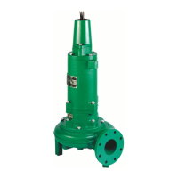
All of the pump fasteners and shafts are made from
corrosion resistant stainless steel, while the pump
castings are made of ASTM A-48 Class 30 cast iron.
The wear ring is brass and all impellers are two
vane enclosed solids handling design made from
ductile iron.
General Installation: Various congurations
and methods of plumbing this series of solids
handling pumps may be used; however, for ease of
installation and service a Myers 4" rail lift-out system
is recommended.
Note: If the hazardous location pumps are used
in conjunction with a rail lift-out system, it must be
an FM approved non-sparking, hazardous location
system. The Myers approved lift-out model is:
SRAX44HH
If these guidelines are not followed, the Factory
Mutual approval is void.
Hazardous Location Service: These pumps are to
be used for handling sewage, wastewater and storm
water only. Do not use in other hazardous locations.
These pumps must be repaired and serviced only
at Myers Authorized Service Centers or at the
Myers factory. Any unauthorized eld repair voids
warranty, hazardous location rating and Factory
Mutual approval.
CAUTION: After the pump is installed and
sewage has entered the basin there are methane
and hydrogen sulde gases, which are poisonous.
Never enter a wet well unless the cover is open
for a sucient period of time to allow fresh air
into the basin. Myers recommends using the rail
lift-out system so that no service is required inside
the basin.
Motor: Each motor is provided with heat sensor
thermostats attached directly to the motor windings.
The thermostats open if the motor windings see
excessive heat and, in turn, open the motor contractor
in the control panel, breaking the power to the pump.
When the motor is stopped due to an overheated
condition, it will not start until the motor has cooled
and the heat sensor reset button is manually pushed
on the front of the Myers control panel. This circuitry
is provided in the Myers control panel designs.
Thermostats are set to open at a temperature of 248°F
(120°C). The maximum contact rating is 18 amps at
115 VAC and 12 amps at 230 VAC. Motor winding
insulation is good for Class H (356°F, 180°C).
Note: Failure to use proper circuitry and to connect
the motor overheat protection in the control panel
would negate all warranties and FM approval.
Motor Seal Failure Warning: The seal chamber is
oil lled and provided with moisture sensing probes
to detect water leakage through the lower shaft seal.
The probes can also detect moisture present in the
upper motor housing.
The presence of water energizes a red seal leak
warning light at the control panel. This is a warning
light only, and does not stop the motor. It indicates
a leak has occurred and the pump must be repaired.
Normally, this indicates the outboard seal has leaked.
Allowing the unit to operate after the warning could
cause upper seal leakage along with motor failure.
The resistance across the moisture sensing (seal
failure) probes should be checked after a seal
leak warning light has lit. This can be done by
disconnecting the red and orange control wires from
the control panel, and measuring the resistance with
an ohmmeter between the wires. If the measured
values are below specication, the pump may have a
lower seal failure and require service.
On the Myers hazardous location control panels
the seal leak test switch tests the seal leak circuit
continuity. When pushed the seal leak test bulb
should light. If the test bulb does not light it means
either the wiring circuitry to the seal leak probes has
been broken or the bulb has burned out.
Note: Myers built control panels supply the correct
circuitry for moisture and heat sensor connections.
Failure to install the correct circuitry with proper
connection would negate warranty and FM approval.
Motor Power Cord, Control Cord and Cord Cap
Assembly: Each motor power cord has 4 conductors:
white, black, red and green. For a three phase motor
the red, black and white conductors connect to the
three line leads, and the green is connected to a good
ground. Interchanging any two line leads will reverse
the rotation of the motor.
Note: Rotation should be clockwise when observed
from the top of the pump. This can be checked by
noting which direction the pump torque is up on
initial starting. A properly rotating pump will torque
counterclockwise upon start.
The control cable has 5 conductors: black, white,
red, orange and green. White and black connect to
the heat sensor terminals in the control panels; red
and orange connect to the seal failure terminals in the
control panel; and the green connects to the ground in
the control panel.
The cord cap is epoxy potted. The cord cap provides
for a sealed wire connection. This allows the cord
cap, with cords, to be removed from the motor. An
approved hazardous location junction box is required
for hazardous locations. The control and power
cables cannot be spliced!
Note: Each cable has a green ground wire and must
be properly grounded per the National Electric Code
and local codes.
 Loading...