23900 Page 3 of 15
Assembly Procedure
1. Spool assembly (0-C204) and spool cam assembly (0-C202)
W17 (t=0.2mm)
2. Top mec. Plate assembly (0-C1)
Pulling back transport indicator
3. Sprocket shaft pin (C40)
Apply screw lock on Set T 1.7 x 1.6
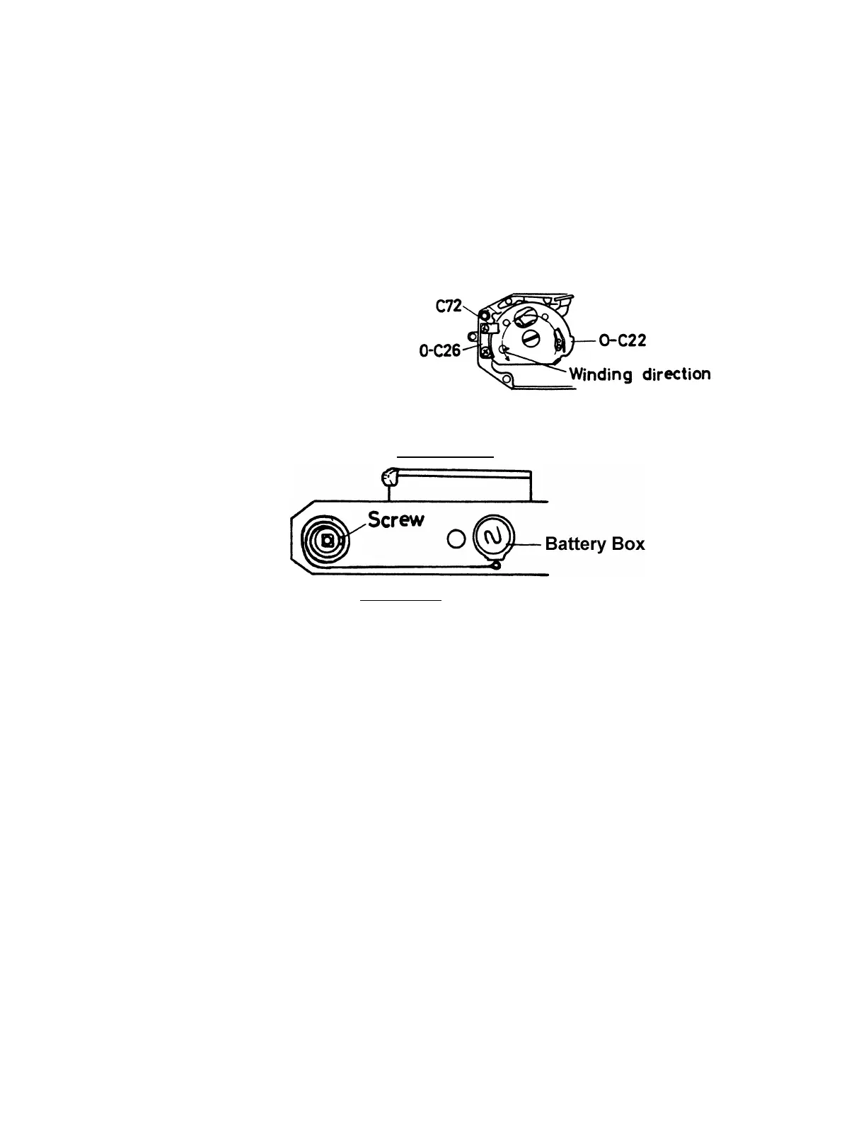
4. Winding shaft assembly (0-C22) - Main gear (C30)
5. Winding stopper assembly (0-C26)
6. Winding spring assembly (0-C12)
Proper tension of the spring is shown in figure.
After installing (0-C12), install (0-C106) and (C207) temporarily.
- 23900K-C207-A
7. Perforation adjustment - Tool 23102-C57-A
Same adjustment with K2 camera.
Choosing proper 2nd gear (C31).
8. Bottom mechanism
a) (C125) - W8 (t=0.1) - Winding hook lever (C108) - W14 (t=0.05, 0.1) -
(C130) - Winding lever ratchet (C107) - LW13 - (C145)
b) (C126) - R lever assembly (0-C105) - LW13
c) Winding guide plate assembly (0-C102) - (C146) - CSS 1.7 x 2.5 - CNS 1.7 x 3
d) Shutter charge lever assembly (0-C129)
Loosening (C207) - (C144) - (0-C129) - fastening (C207)
When fastening (C207), winding shaft should be in the wound position, at
the same time, mirror charge lever (0-C102) should be moved to a correct
position
9. Shutter release plate
Release plate restitution spring (A510)
(Take care to install spring in correct direction)
Release plate assembly (A5000
(Take care not to bend winding hook lever (C108).)
Guide screw (A507), connection spring (A511)
(Engaging (A510) to (A500).)
10. Bottom release assembly (0-C147) - CNM 1.7 x 2.2, CNM 1.7 x 2.8
Winding shutter a little