23900 Page 4 of 15
11. Shutter block (E000) - CNL-D 1.7 x 3 x3
Light seal plate (A8)
12. Bulb actuator plate (A504) Temporary installation
- CNL-D 1.4 x 2
13. Back cover assembly (A200)
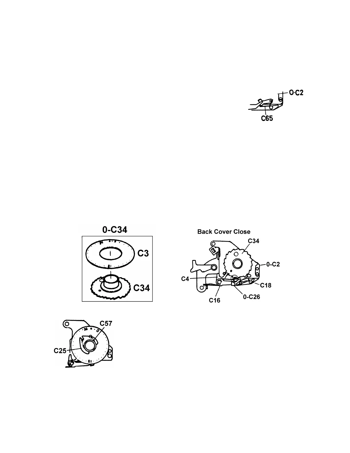
14. Winding seat assembly (0-C2) - (C53), (C146), CNS 1.7 x 3
Install (0-C2) with back cover open
Winding lever click cam assembly (0-C5)
Winding lever friction spring (C7)
Engage transporting claw spring (C65)
15. Counter transporting adjustment
a) Check the function of counter dial stopper lever (C4) and transporting
claw assembly (C18).
b) If the vertical black lever of (0-C26) is bent forward, bend it straight.
c) Adjust the counter transporting function using the temporary counter
transporting gear (C34).
When back cover is closed, receiving claw (C16) and transporting claw (C18)
should be engaged to the first tooth of (C34) simultaneously with enough
gearing portion. Bend the tip of the claw which couples with the gear (C34),
If not enough gearing portion.
When back cover is opened, claw tip of (C16) must detach from the gear (C34)
with a clearance of about 0.5mm.
If there is not enough clearance, bend the other end of (C16) opposite from
the claw as shown in the figure.
16. Counter dial
Counter dial assembly (0-C34)
Counter dial spring (C57)
Counter retainer plate (C25)
(C25) is installed in left side gutter as shown in figure.
Give the spring (C57) 1/2 or 3/4 turns of tension.
17. Bulb off adjustment (Winding lever is at pre-advance position.)
After releasing the first curtain, adjust "B" off position with eccentric
screw riveted on bulb actuator plate (A504). When shutter rod comes back,
0.2mm clearance is necessary after releasing the 2nd curtain.
 Loading...