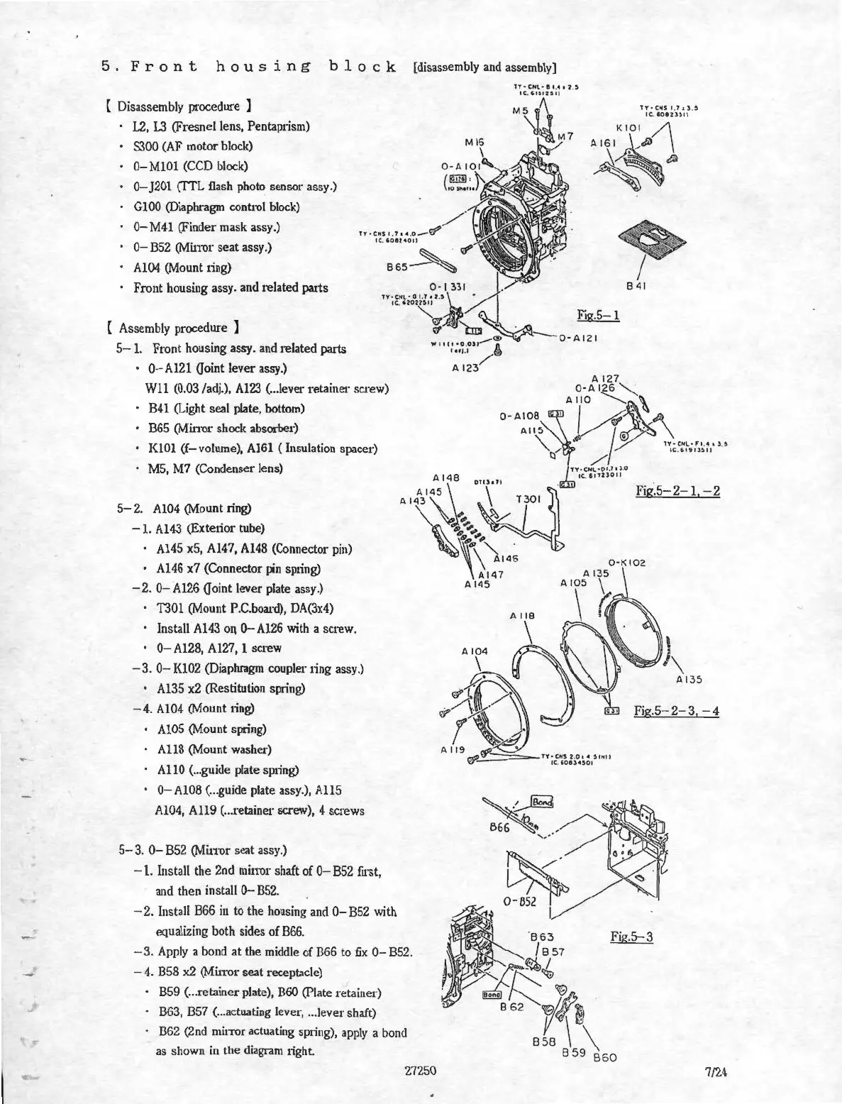
5 . F r
on
t h o u s i n g b 1 o c k [disassembly
and
assembly)
( Disassembly procedure
J
1.2,
L3
(Fresnel lens, Pentaplism)
S300 (AF motor block)
0- MlOl
(CCD
block)
0-
J201 (TTL flash photo sensor assy.)
GlOO
(Diapluc1gm
control block)
0- M41 (Finder mask assy.)
0-
B52
(Mi
nor
seat assy.)
Al04 (Mount 1ing)
Front housing assy. and related patts
Assembly procedure ]
5-1.
Front housing assy. and
re
lated patts
·
0-Al21
Goint lever assy.)
Wll
(0.03 /adj.), Al23 ( ... lever retainer screw)
B41
(Light seal plate, bottom)
B65
(Mirrnr shock absorber)
KlOl (f-volume), Al61 (Insulation spacer)
MS,
M7
(Condenser lens)
5-
2.
Al04 (Mount ring)
-1.
Al43 (Exte1ior tube)
· Al45 x5, Al47, Al48 (Connector
pin)
• Al46 x7 (Connector
pn
sp1ing)
-
2.
0-
Al26 Ooint lever plate assy.)
T301 (Mount P.C.board), 0A(3x4)
· Install Al43
Ol\
O-Al26
with
a screw.
·
0-Al28,
Al27, 1 screw
-3.
0-
Kl02 (Diaphragm coupler 1ing assy.)
· Al35 x2 (Restitution spring)
-
4.
Al04 (Mount ting)
Al05 (Mount spiing)
All8
(Mount washer)
AHO ( ... guide plate spiing)
0-Al08
( ... guide plate assy.),
All5
Al04,
All9
( ... retainer screw), 4 screws
5-3.
0-
852
(Min-or seat assy.)
-
1.
Install the 2nd
min'Or
shaft of
0-
B52
fast,
and then install
0-
B52.
-
2.
Install B66
in
to the housing and
0-
B52
with
equalizing both sides of 866.
-3
.
Apply
a bond
at
the middle of B66 to
fix
0-
B52.
-
4.
B58
x2
(Mirror seat receptacle)
859
( ... retainer plate), B60 (Plate retainer)
863,
857
( ... actuating lever, .. .lever shaft)
862
(2nd
muTOr
actuating sp1ing), apply a bond
as shown in the
diagram
1ight.
27250
lY•CH\.·t•
.
4•
l)
CC..•l>IUtl
M~
,\
~M7
l't·
c .. s
t,
l . ) , $
•C.IO
IU)
tJ
KIOI
/\
A 161
1..,Jl'
\
~~
Fig.5- 2- 3, - 4
7/24