EasyManua.ls Logo

peplink MAX BR1 Mini User Manual

peplink MAX BR1 Mini
2 pages
To Next Page IconTo Next Page
Page #1 background imageLoading...
Page #1 background image
Have questions? Call Powerful Signal at 435-634-6800 or visit us online at PowerfulSignal.com
Figure 4
Power up the router
Connect the power supply to the router’s DC IN port. (Figure 4) The release
clip must be facing up for the connector to click into place. Plug the other end
of the power supply into an AC wall outlet.
Once the router is connected to a power source, the Status light will turn red.
Within 3 to 5 minutes, all three lightsStatus, Wi-Fi, and Cellularshould
turn green, indicating that the router is functioning properly.
− +
DC IN
Figure
3
LTE antenna connectors
WiFi antenna connectors
Attach the antennas
Attach the two flat-end LTE paddle antennas to the router’s threaded Main
(top left) and Diversity/Aux (top right) connectors and hand tighten them.
(Figure 3)
If your system includes a separate MIMO antenna, skip this step and connect
the MIMO antenna to the Main and Diversity/Aux connectors instead.
Attach the two rounded-end WiFi paddle antennas to the router’s threaded
Wi-Fi Antenna A (bottom left) and Wi-Fi Antenna B (bottom right)
connectors and hand tighten them. (Figure 3)
Figure 2
Figure 1
Install your SIM card
Use a small Phillips screwdriver to loosen the Cellular SIM cover at the end
of the router. Rotate the cover to expose the SIM slots. (Figure 1)
Insert an activated nano SIM card into Slot A, beveled corner first and the
gold circuit side facing down. Push the card into the slot with your fingernail
until it clicks into place. (Figure 2)
If you use a second card in
Slot B
, insert it beveled corner first with the gold
circuit side facing up. Push until it clicks into place.
Rotate the Cellular SIM cover back into position over the SIM slots.
Hand-tighten the cover with the Phillips screwdriver.
Tip:
Keep the manufacturer’s
box and all its contents.
The packaging contains
important information for
technical support and
reordering.
Box contents
TS007001
Peplink MAX BR1 Mini HW3 CellularWiFi Router
Quick Setup Guide
Question and Answer IconNeed help?

Do you have a question about the peplink MAX BR1 Mini and is the answer not in the manual?

peplink MAX BR1 Mini Specifications

General IconGeneral
ModelMAX BR1 Mini
CategoryWireless Router
Ethernet Ports1x GE WAN, 1x GE LAN
GPSYes
Cellular Connectivity4G LTE
USB Port1x USB 2.0
Wi-Fi802.11ac/a/b/g/n
Power InputDC 10V – 30V
Power Consumption12W
Operating Temperature-40° to 149°F / -40° to 65°C
WAN Interface1 x Gigabit Ethernet
Ethernet LAN1 x Gigabit Ethernet
Wireless Standards802.11b/g/n
Max Data Rate150Mbps
SIM Slots1
Weight300g

Summary

Install SIM Card

SIM Card Insertion

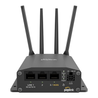
Insert an activated nano SIM card into Slot A, beveled corner first, gold circuit side facing down.

SIM Cover Securing

Rotate the Cellular SIM cover back into position and hand-tighten it with a screwdriver.

Attach Antennas

LTE Antenna Connection

Attach the two flat-end LTE paddle antennas to the Main and Diversity/Aux connectors.

WiFi Antenna Connection

Attach the two rounded-end WiFi paddle antennas to the Wi-Fi Antenna A and B connectors.

Power Up Router

Power Connection

Connect the power supply to the router's DC IN port and plug into an AC wall outlet.

Status Indicator Lights

Observe Status, Wi-Fi, and Cellular lights turn green within 3-5 minutes for proper function.

Connect to WiFi Network

Initial WiFi Connection

Connect to the PEPLINK_xxxx network using the AP Password from the router's label.

Log In and Change Passwords

Router Login

Access the web dashboard at 192.168.50.1 and log in with default credentials.

Admin Password Change

Change the default admin password for router dashboard access to a strong, secure password.

WiFi AP Password Change

Change the WiFi AP password for connecting devices to the router's wireless network.

Advanced Settings & Reset

Accessing Advanced Settings

Modify advanced router settings via the web-based dashboard after logging in.

Factory Reset Procedure

Perform a factory reset using a paperclip in the reset hole to restore default configuration.

Related product manuals