2024-03
16
ARS*-B2-IA*
Installation
6-pole auxiliary power connector
The isolation of installed wires must finish at the terminal cage. Alternatively, isolated wire end
ferrules can be used.
The terminal cages of unused terminal connections for PWR A and PWR B must be covered,
for example, with isolated wire end ferrules. Crimp the insulation tube so that no conductive
parts of the wire end ferrule are exposed.
To comply with degree of protection IP30, cover the connectors on PWR A and PWR B and, if
used, the connector for status indicator output. During maintenance, the cover must prevent a
screwdriver from making unintended contact with conducting non-intrinsically safe compo-
nents of the power connector.
Versions with Spring Terminals (ARS*-2)
Ethernet ports P1 ... P4
Not used Ethernet ports P1 ... P4 have to be equipped with the corresponding covers:
• Protection cover ACC-PC-45 for Ethernet ports P1 and P2
• Protection cover ACC-PC-SFP for Ethernet ports P3 and P4
6-pole auxiliary power connector
The isolation of installed wires must finish at the terminal cage. Alternatively, isolated wire end
ferrules can be used.
The terminal cages of unused terminal connections for PWR A and PWR B must be covered,
for example, with isolated wire end ferrules. Crimp the insulation tube so that no conductive
parts of the wire end ferrule are exposed.
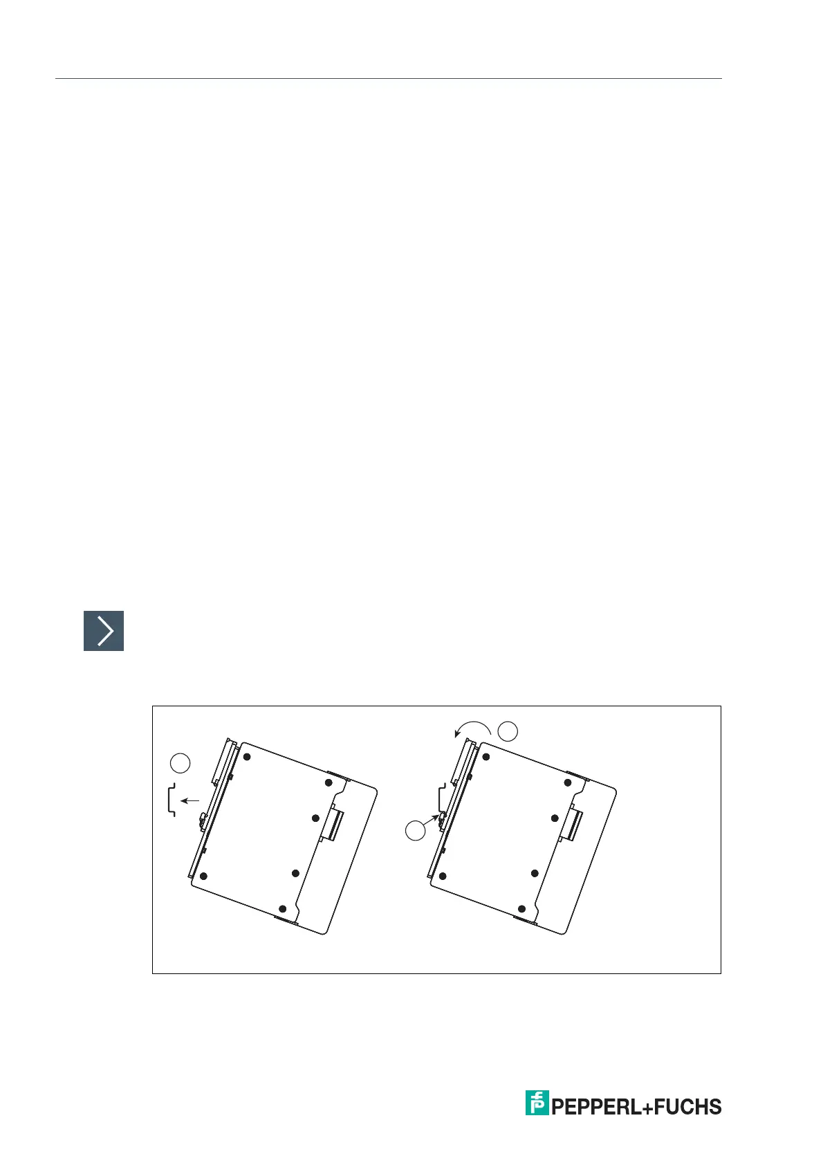
3.3 Mounting and Dismounting
Mounting or Dismounting Rail Field Switches
Mounting DIN mounting rail
The rail field switches are designed for mounting on a 35 mm DIN mounting rail in accordance
with EN 50022.
Figure 3.1
1.
Position the rail field switch on the DIN mounting rail.