2024-03
22
ARS*-B2-IA*
Installation
• Ensure that connectors are mechanically locked
• Torque required for tightening the retaining screws: 0.3 Nm
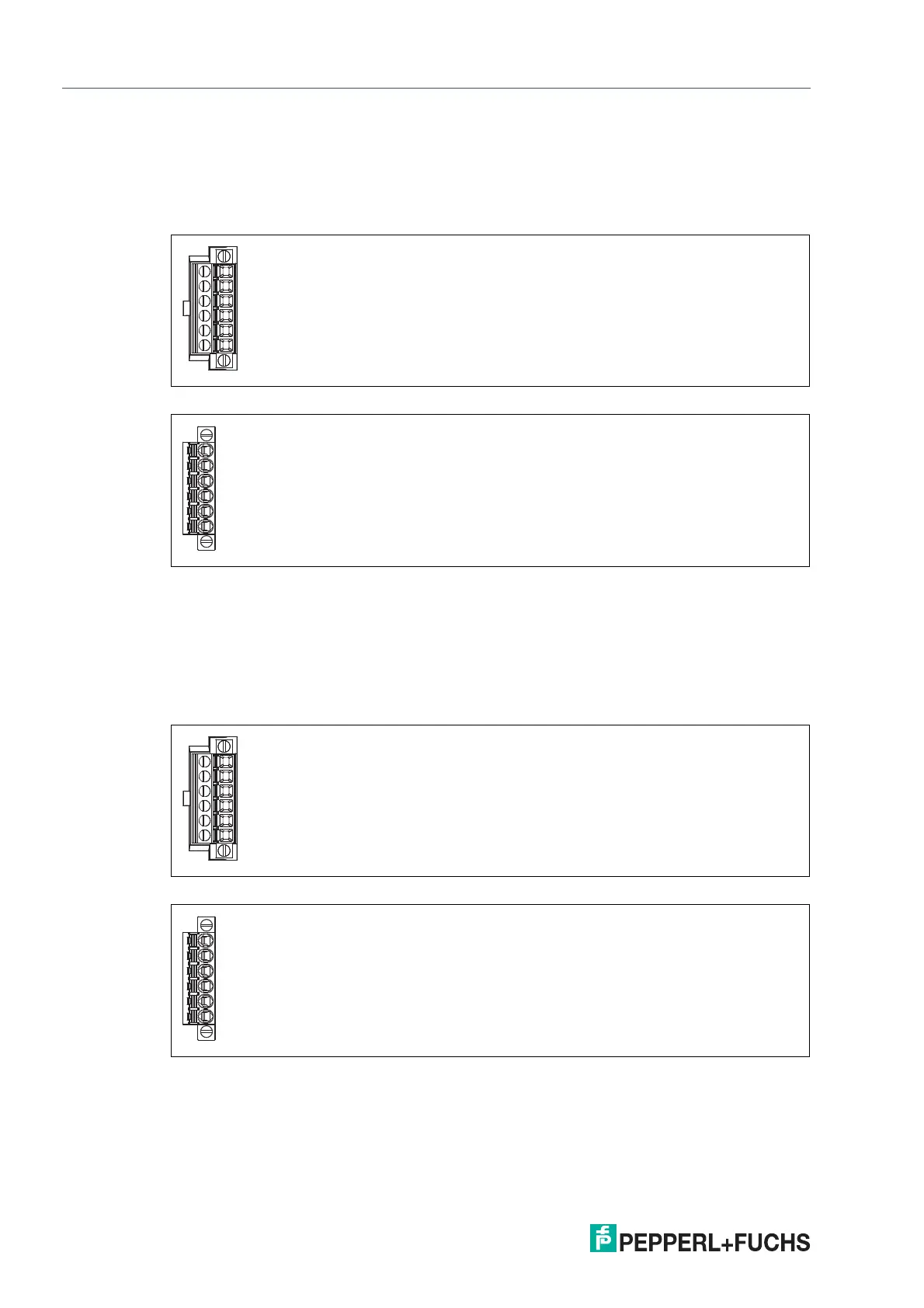
Auxiliary Power Connection
The rail field switch provides redundant auxiliary power supply inputs PWR A and PWR B.
Figure 3.6 Connector with screw terminals
Figure 3.7 Connector with spring terminals
The rail field switch must be supplied with a DC voltage U
n
= 20 V ... 60 V that meets the
requirements for safety extra-low voltage (SELV) or protective extra-low voltage (PELV) and not
exceed a maximum voltage of 60 V DC even under fault condition. At the power terminal the
cross section of the cables must be chosen in accordance with the maximum fuse protection of
the external circuit.
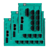
Status Indication Output
Figure 3.8 Connector with screw terminals
Figure 3.9 Connector with spring terminals
The rail field switch provides a relay contact output for status indication.