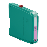
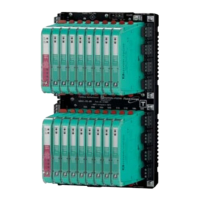
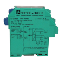
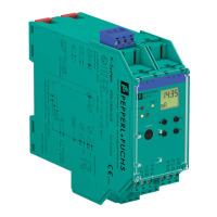
Functional Safety HiD2022*, KFD2-STC5-(Ex)*, KFD2-STV5-(Ex)*
Planning
2017-09
15
SIL 3 Application
SIL 3 can be reached if the two outputs of the device are connected to the same
control interface and evaluated if the deviation remains below 2 %.
• The device shall claim less than 10 % of the total failure rate for a SIL 3 safety
loop.
• For a SIL 3 application operating in low demand mode the total PFD
avg
value
of the SIF (Safety Instrumented Function) should be smaller than 10
-3
, hence
the maximum allowable PFD
avg
value would then be 10
-4
.
• For a SIL 3 application operating in high demand mode the total PFH value of
the SIF should be smaller than 10
-7
per hour, hence the maximum allowable
PFH value would then be 10
-8
per hour.
• Since the safety loop has a hardware fault tolerance of 0 and it is a type A
device, the SFF must be > 90 % according to table 2 of IEC/EN 61508-2 for a
SIL 3 (sub) system.
3.3 Safety Function and Safe State
Safety Function
The device transfers analog signals from the input to the output with a deviation of
less than 2 %.
Safe State
Ensure that the emergency shutdown (ESD) reacts adequately when the outputs
are
• <4mA or >20mA,
•<1V or >5V,
• <2V or >10V.
Failures that introduce the safe state show that either the device or the attached
periphery is defective as a live zero signal is expected. Due to this, these failures
are counted as dangerous detected failures for the system.
Reaction Time
The reaction time for all safety functions is < 100 ms.
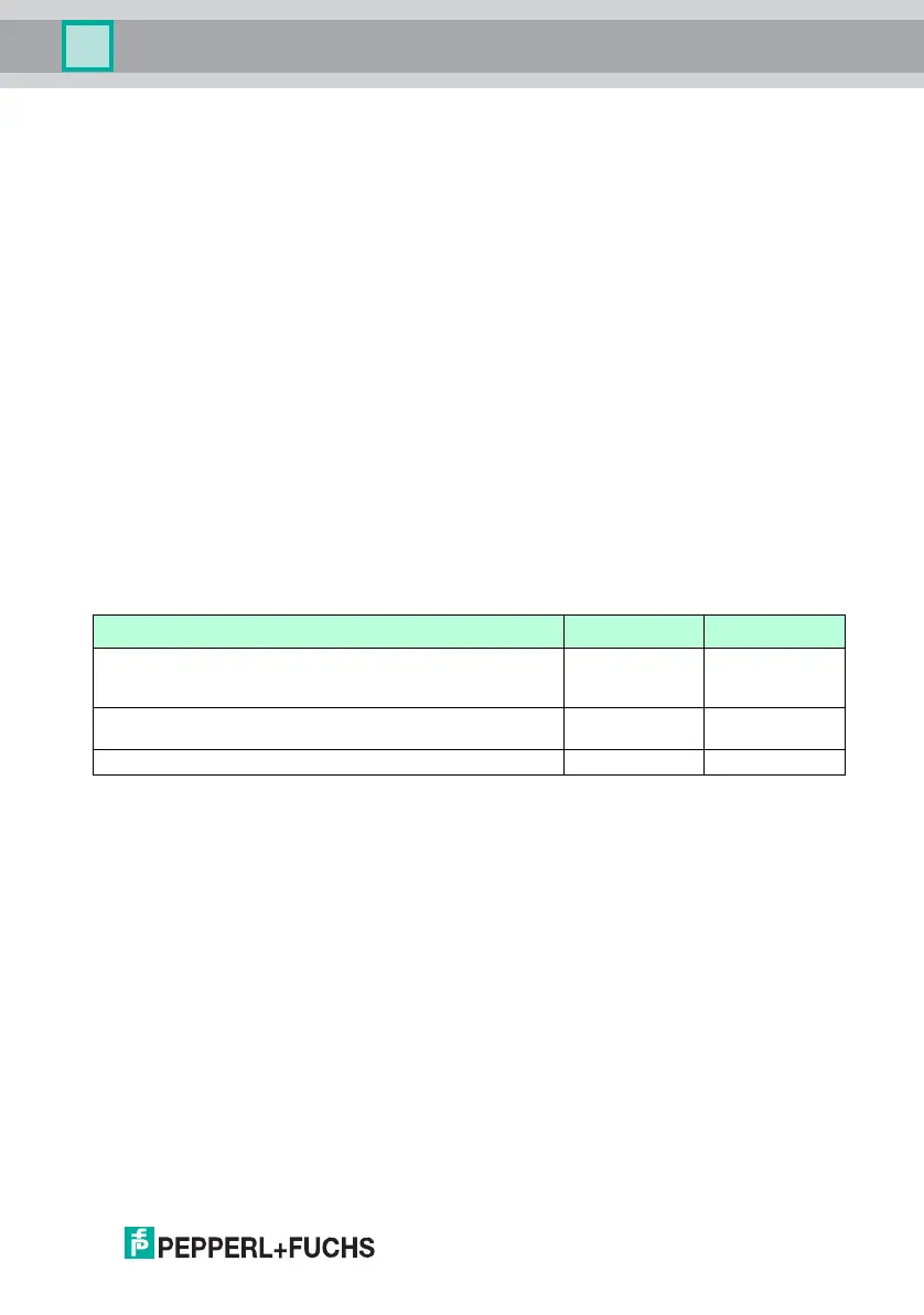
Device Input signals Output signals
KFD2-STC5-1, KFD2-STC5-Ex1, KFD2-STC5-Ex1.H
KFD2-STC5-1.2O, KFD2-STC5-Ex1.2O, KFD2-STC5-Ex1.2O.H,
HiD2022, HiD2022SK, KFD2-STC5-2, KFD2-STC5-Ex2
0/4 mA to 20 mA 0/4 mA to 20 mA
KFD2-STV5-1-1, KFD2-STV5-Ex1-1, KFD2-STV5-Ex1.2O-1,
KFD2-STV5-2-1, KFD2-STV5-Ex2-1
0/4 mA to 20 mA 0/1 V to 5 V
KFD2-STV5-Ex1-2, KFD2-STV5-Ex1.2O-2, KFD2-STV5-Ex2-2 0/4 mA to 20 mA 0/2 V to 10 V
Table 3.1