2017-09
22
Functional Safety HiD2022*, KFD2-STC5-(Ex)*, KFD2-STV5-(Ex)*
Operation
Proof Test Procedure
1. Put out of service the entire safety loop. Protect the application by means of
other measures.
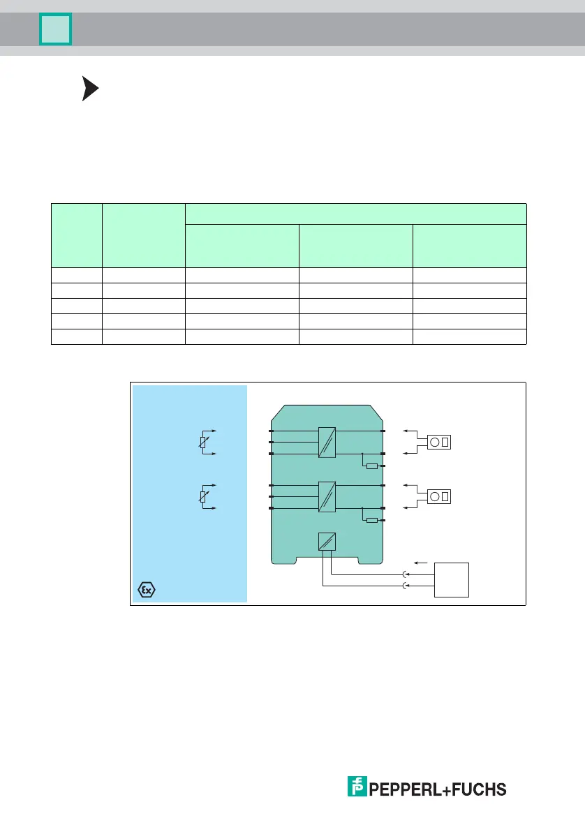
2. Prepare a test set-up, see figures below.
3. Test the devices. Verify the current values as given in table below.
4. Set back the device to the original settings for the application after the test.
Proof Test for 1- and 2-Channel Devices
Figure 5.1 Proof test set-up for KFD2-STC5-(Ex)*-*(.H)
Usage in Zone 0, 1, 2/Div. 1, 2 only for KFD2-STC5-Ex1, KFD2-STC5-Ex1.H, and
KFD2-STC5-Ex2
The KFD2-STC5-1, KFD2-STC5-Ex1, and KFD2-STC5-Ex1.H devices have no
second channel.
Step No. Input value (mA) Output value
Current source/current
sink (mA) for
KFD2-STC5-(Ex)*-*(.H)
Voltage source (V) for
KFD2-STV5-(Ex)*-1
Voltage source (V) for
KFD2-STV5-(Ex)*-2
1 20.0 20.0 ± 0.4 5.0 ± 0.1 10.0 ± 0.2
2 12.0 12.0 ± 0.4 3.0 ± 0.1 6.0 ± 0.2
3 4.0 4.0 ± 0.4 1.0 ± 0.1 2.0 ± 0.2
4 23.0 23.0 ± 0.4 5.75 ± 0.1 11.5 ± 0.2
5 0 < 0.2 < 0.1 < 0.1
Table 5.1
KFD2-STC5-Ex2
Zone 0, 1, 2
Div. 1, 2
Zone 2
Div. 2
I
supply
1
3
2
4
6
5
7-
8+
9
250 Ω
10-
11+
12
250 Ω
14+
15-
Signal calibration
4 mA ... 20 mA
24 V DC
Power
supply
Multimeter
(mA)
Multimeter
(mA)