Subject to reasonable modifications due to technical advances. Copyright Pepperl+Fuchs, Printed in Germany
Pepperl+Fuchs Group • Tel.: Germany +49 621 776-0 • USA +1 330 4253555 • Singapore +65 67799091 • Internet http://www.pepperl-fuchs.com
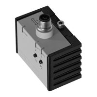
Inclination sensor INX360D-F99-I2E2-V15
2
Release date: 2011-08-17 14:11 Date of edition: 2011-08-17 201503_eng.xml
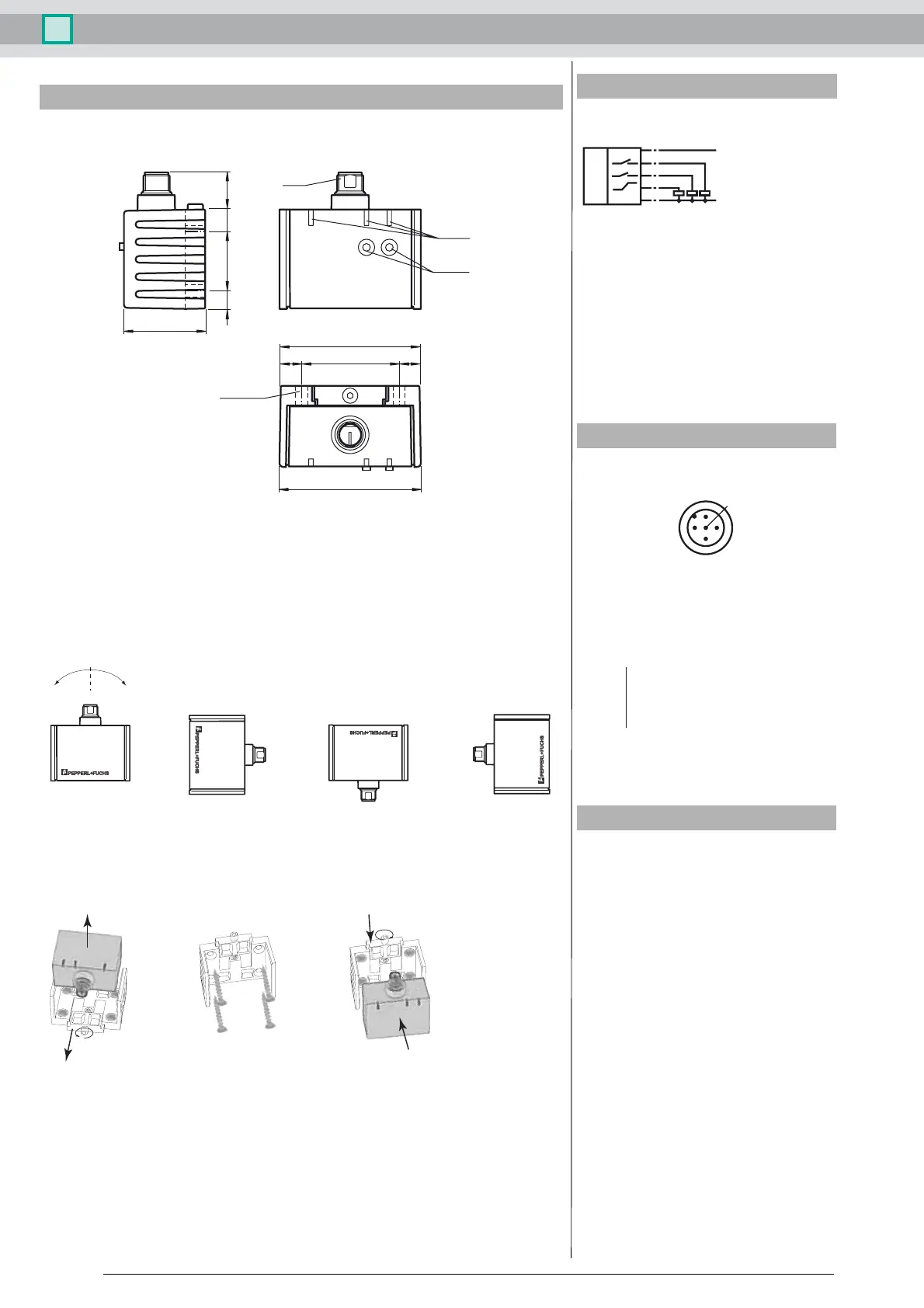
Sensor Orientation
In the default setting the zero position of the sensor is reached, when the electrical connection faces straight upwards.
- On request, all required mounting positions can be preset at the factory.
For example: X = 0 if the electrical connection points straight downwards.
X Orientation
Mounting of the sensor
Inclination sensors from the -F99 series consist of a sensor module and accompanying cast aluminum housing. Select a flat surface
with minimum dimensions of 70 mm x 50 mm to mount the sensor.
Mount the sensor as follows:
1. Loosen the central screw under the sensor connection.
2. Slide back the clamping element until you are able to remove the sensor module from the housing.
3. Remove the sensor module from the housing
4. Position the housing at the required mounting location and secure using four countersunk screws. Make sure that the heads
of the screws do not protrude.
5. Place the sensor module in the housing.
6. Slide the clamping element flush into the housing. Check that the sensor element is seated correctly.
7. Finally tighten the central screw.
The inclination sensor is now mounted correctly.
LED display
Dimensions
Button
104510
64
65
4 x ø 5.5
M12
7 30 718.5
37
LEDs
+
-
X = 0° X = 90° X = ±180° X = 270° (-90°)
5.
7.
6.
4.
1.
2.
3.
Electrical connection
Pinout
Accessories
V15-G-2M-PUR
Cable socket, M12, 5-pin, PUR cable
V15-W-2M-PUR
Cable socket, M12, 5-pin, PUR cable
Standard symbol/Connection:
+U
B
Out 2
Out 1
Analogue output
-U
B
I
1
3
2
4
5
1
3
4
5
2
1 BN
2 WH
3 BU
4 BK
5 GY
Wire colors in accordance with EN 60947-5-2
(brown)
(white)
(blue)
(black)
(gray)
 Loading...