Subject to reasonable modifications due to technical advances. Copyright Pepperl+Fuchs, Printed in Germany
Pepperl+Fuchs Group • Tel.: Germany +49 621 776-0 • USA +1 330 4253555 • Singapore +65 67799091 • Internet http://www.pepperl-fuchs.com
Inclination sensor INX360D-F99-I2E2-V15
3
Release date: 2011-08-17 14:11 Date of edition: 2011-08-17 201503_eng.xml
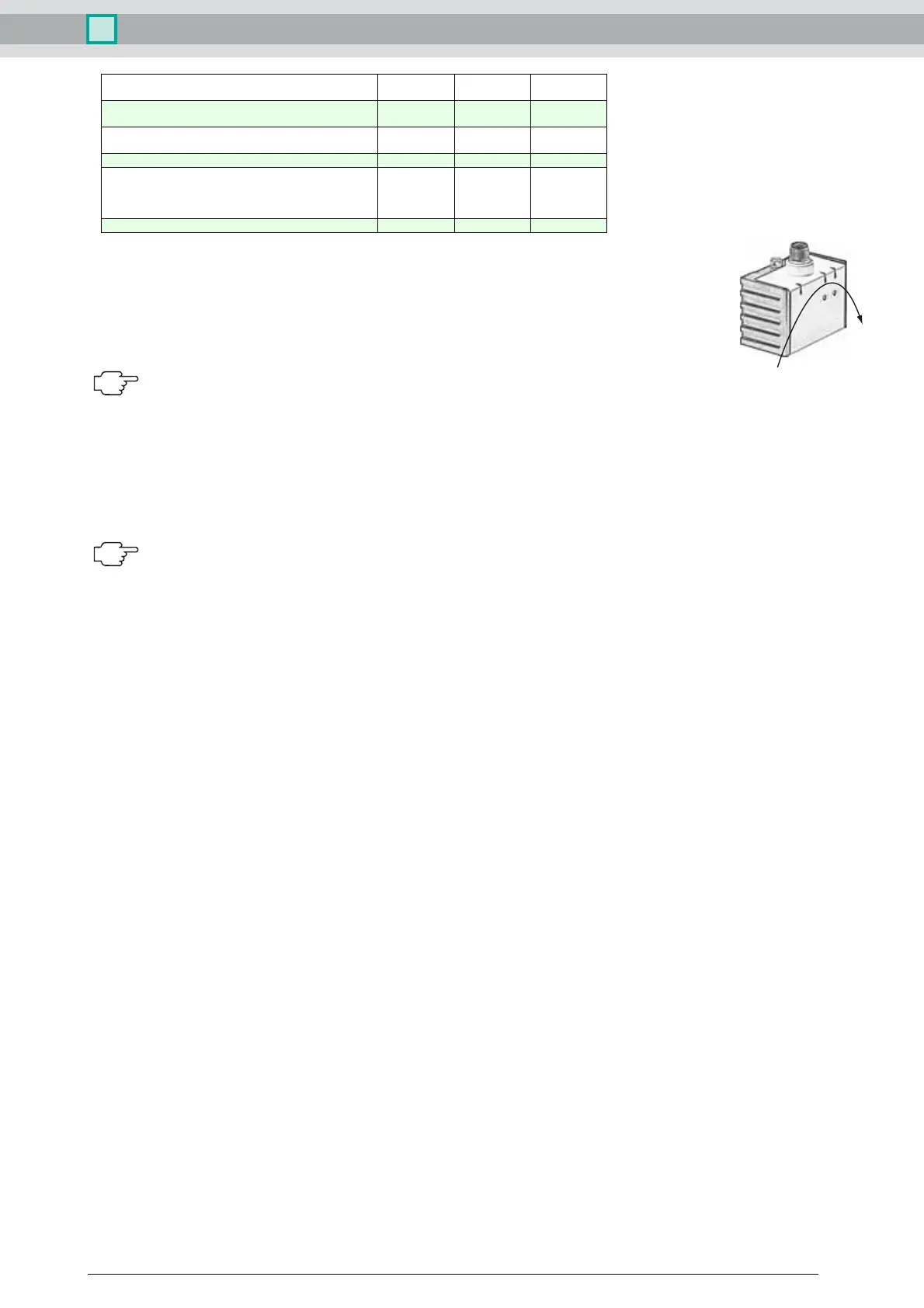
Axis definition
The definition of the X-axis is shown on the sensor housing by means of an imprinted and labeled double arrow. The figure shows the clockwise direction of
rotation.
Teach-in of switching points (output S1)
1. Press key T1 > 2 s (see LED display)
2. Move sensor to switching position 1
3. Press key T1 briefly. LED "out 1" lights for 1.5 s as confirmation. Switching point 1 has been taught
4. Move sensor to switching position 2
5. Press key T1 briefly. LED "out 1" lights for 1.5 s as confirmation. Switching point 2 has been taught
6. Sensor returns to normal operation (see LED display)
If the switching points are taught in clockwise direction, the switching output between these switching points works as a NO contact. If the switching
points are taught in anticlockwise direction, the switching output between these switching points works as a NC contact.
Teach-in of switching points (output S2)
Similar to the process for "Teach-in of switching points (output S1)“, but with key T2 instead of key T1.
Teach-in of analog limits
1. Activate the teach-in mode for the analog limits by simultaneously pressing keys T1 and T2 until the green LED is extinguished and the two yellow LEDs flash. Then release the keys.
2. Press key T1 > for 2 s (see LED display)
3. Move the sensor into the position of minimum evaluation limit
4. Press key T1 briefly. LED "out 1" lights for 1.5 s as confirmation. The minimum evaluation limit has been taught. In this position the analog output will provide its minimum output value.
5. Move the sensor into the position of maximum evaluation limit
6. Press key T1 briefly. LED "out 1" lights for 1.5 s as confirmation. The maximum evaluation limit has been taught. In this position the analog output will provide its maximum output value.
7. Sensor returns to normal operation (see LED display)
If the sensor inclination exceeds one of the analog limits, the last value of the analog output is retained.
Resetting the sensor to factory settings
1. Press keys T1 and T2 > 10 s (see LED display)
2. The sensor has been reset when the green LED "Power" lights again after approx. 10 s.
Undervoltage detection
If the supply voltage falls below a value of approx. 7 V, all outputs and yellow LEDs are deactivated. The green "power" LED flashes rapidly. If the supply voltage falls below a value of approx. 8 V, the
sensor continues with normal operation.
Displays dependent on the operating state LED green:
Power
LED yellow
out 1
LED yellow
out 2
Teach-in of switching points (output S1):
Teach-in of switching points (output S2):
off
off
flashes
off
off
flashes
Activate teach-in mode for analog limits:
Teach-in of analog limits
off
off
flashes
flashes
flashes
off
Normal operation on switchingstate switchingstate
Reset to factory settings:
2 s ... 10 s
> 10 s ... end of reset process
Followed by normal operation
off
flashes
flashes
off
flashes
off
Undervoltage flashes off off
X
 Loading...