DOCT-0187Y 2023-12
44
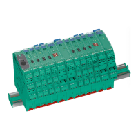
K-System – Isolated Barriers
Technical Specifications
Mechanical Specifications
Mounting
• Snap-on 35 mm DIN mounting rail according to EN 60715. Can be mounted horizontally
or vertically, side by side.
• Panel mount: The lugs on the base of the isolator must be extended and used for mounting
purposes with 3 mm screws.
• K-MS mounting base for screw attachment
Housing Material
• Polycarbonate (PC)
Dimensions
• Dimension drawings please refer to chapter Dimensions.
Protection Degree
• IP20 according to EN 60529
Connection
• KH* devices: self-opening terminals for max. core diameter of 1 x 2.5 mm
2
(14 AWG)
• KF* and KC* devices: removable connector with integrated self opening terminals for leads
of up to a max. of 1 x 2.5 mm
2
(14 AWG)
• Observe the tightening torque of the terminal screws. The tightening torque is
0.5 Nm to 0.6 Nm.
Fire Protection Class
• Housing: V2 according to UL 94 standard. Unless stated otherwise all details relate
to the reference conditions.
Labeling
Place for labeling on the front side:
• KC devices (12.5 mm): label 22 mm x 9 mm
• KF devices (20 mm and 40 mm): label 22 mm x 16.5 mm
• All KC and KF devices: adhesive label 22 mm x 11, can only be used on devices
with a transparent front flap
• KF devices: label 18 mm x 8 mm, can only be used on devices without a transparent
front flap
Note
See corresponding datasheets for further information.