Do you have a question about the Pepperl+Fuchs 6000 SERIES and is the answer not in the manual?
Explains the meaning of various symbols used in the manual.
Outlines relevant EU directives for explosive atmospheres.
Specifies prerequisites for safe handling and operation.
Defines obligations for safe operation and maintenance.
Explains the principle of pressurized enclosures for safety.
Details ATEX and UL markings for control units.
Details ATEX and UL markings for specific control units.
Details ATEX and UL markings for the user interface.
Details ATEX and UL markings for the ISB termination board.
Details ATEX and UL markings for the temperature sensor.
Details ATEX and UL markings for the TSEN sensor.
Details ATEX and UL markings for the vent.
Details the pneumatic manifold and its parts.
Information about the EPV-6000 vent.
Describes temperature sensors and hubs.
Provides crucial guidelines for electrical wiring.
Details specific wiring instructions for intrinsically safe circuits.
Specifies requirements for the protective gas supply.
Details pneumatic connections and fittings.
Explains how to adjust system pressure.
Guides on manifold assembly and mounting.
Instructions for mounting the vent externally.
Instructions for mounting the vent internally.
Lists and identifies key components of the kit.
Specifies the EPV-6000 vent requirement for the kit.
Wiring guidelines for component kit installations.
Specific wiring instructions for intrinsically safe circuits in the kit.
Instructions for mounting the user interface panel.
Flowchart illustrating power-on sequence.
Flowchart illustrating power-off sequence.
Describes the system's components and overall operation.
Details the function and availability of the EPCU.
Explains the UIC's programming and operational features.
Configuration for system units (English/Metric).
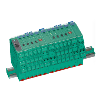
Provides physical dimensions of the control unit.
Provides dimensions for the EPCU with enclosure.
Provides dimensions for the ISB termination board.
Explains how to interpret control unit model numbers.
Explains how to interpret vent model numbers.
Diagrams and specs for single enclosure connections.
Diagrams and specs for multiple enclosure connections.
Provides tips for proper tubing and piping installation.
Configuration options for Input 1.
Configuration options for Input 2.
Configuration options for Input 3.
Configuration options for Input 4.
Configuration options for Temp Input 1.
Configuration options for Output 1.
Configuration options for Output 2.
Configuration options for passwords.
Configuration options for system language.
Configuration options for bypass control.
Option to restore factory defaults.
| Product Category | Inductive Sensors |
|---|---|
| Series | 6000 |
| Type | Cylindrical |
| Housing Material | Nickel-plated brass or stainless steel |
| Protection Rating | IP67 |
| Operating Voltage | 10-30 V DC |
| Output Type | PNP or NPN |
| Switching Frequency | 1 kHz |
| Connection Type | Cable or Connector |
| Temperature Range | -25°C to +70°C |