20
6000 Series Purge/Pressurization System
I/O Manual
The maximum distance between the control
unit and the termination board is 3 meters.
6000-ISB-… must be installed within an IP20
enclosure. See “conditions of safe use” when
mounting in a dust environment.
Power to
EPCU
Prewired
Enclosure
Contacts
(2) N.O.
Aux
Output 1
(1) SPDT
Aux
Output 2
(1) SPDT
L1
GND
GND
GND
GND
N
IS PWR 1
IS PWR 2
IS PWR 3
GND
In 1
In 2
In GND
In 3
In 4
Com B
Com A
Val +
Val -
1
2
3
4
5
6
7
8
9
10
11
12
13
Temp
Module
User
Interface
1
2
3
4
5
6
7
8
9
10
11
12
13
1
2
3
4
5
6
7
8
9
10
11
12
13
IS Solenoid
Valve
1
2
3
4
5
6
7
8
9
10
11
12
13
Vents
Vent 1
Vent 2
1
2
3
4
5
6
7
8
9
10
11
12
13
Inputs 1-4
1
2
3
4
5
6
7
8
9
10
11
12
13
(BN)
(BN)
(BN)
(BN)
(BU)
(BU)
(BK)
(WH)
(BN)
(BK)
(BU)
(WH)
(BU)
(BK)
(WH)
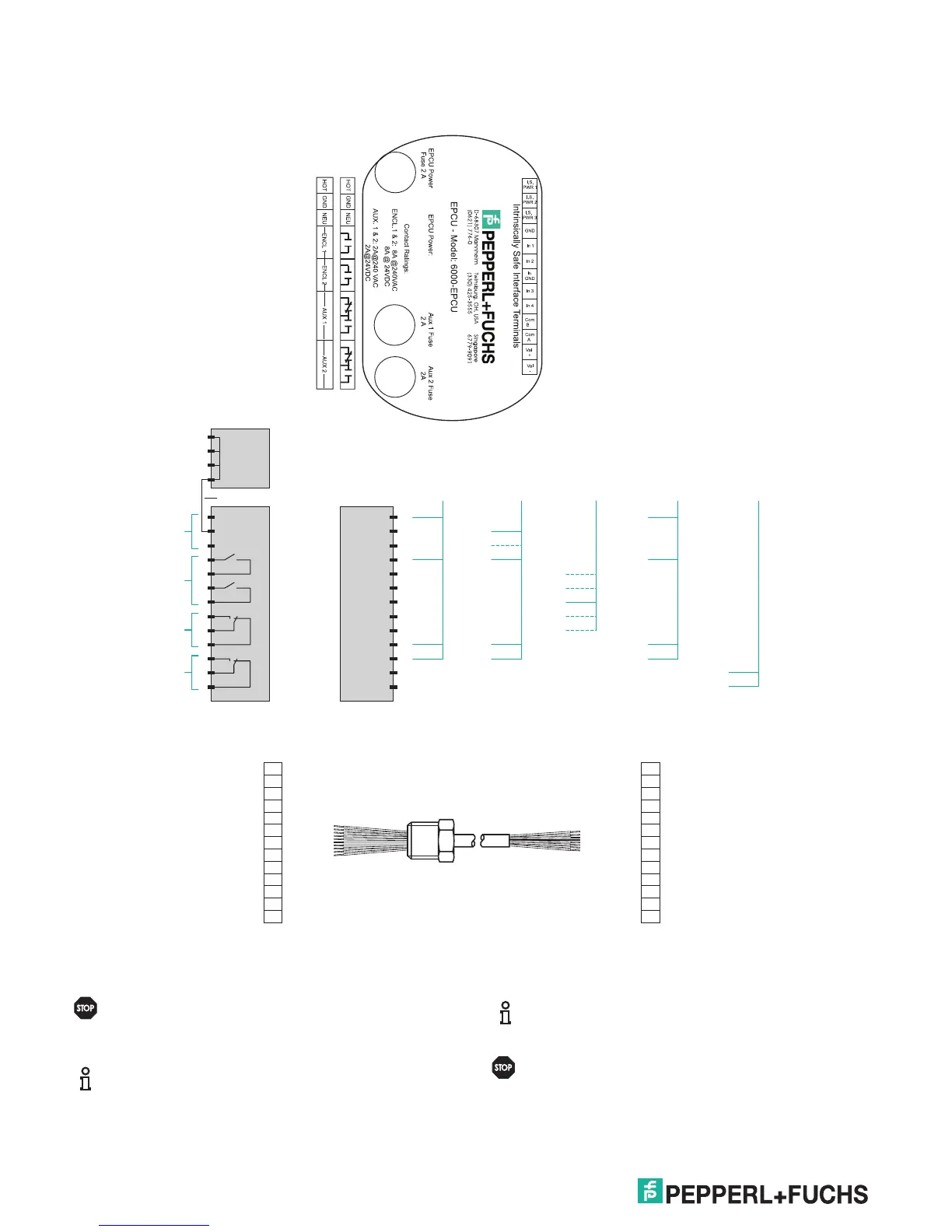
Electrical installation - power and I.S. wiring
Requires standard explosion-proof seals to
explosion-proof/ameproof enclosure at a
maximum distance of 18" (457.2 mm).
When removing the terminal block from the
EPCU stack, place your hand on top of the
plastic to support the stack when lifting the
terminal block.
Power to
EPCU
Prewired
Contacts
(2) N.O.
Aux
Output 1
(1) SPDT
Aux
Output 2
(1) SPDT
L1
GND
GND
GND
GND
N
IS PWR 1
IS PWR 2
IS PWR 3
GND
In 1
In 2
In GND
In 3
In 4
Com B
Com A
Val +
Val -
1
2
3
4
5
6
7
8
9
10
11
12
13
Temp
Module
User
Interface
1
2
3
4
5
6
7
8
9
10
11
12
13
1
2
3
4
5
6
7
8
9
10
11
12
13
Valve
1
2
3
4
5
6
7
8
9
10
11
12
13
Vents
Vent 1
Vent 2
1
2
3
4
5
6
7
8
9
10
11
12
13
Inputs 1-4
(BN)
(BN)
(BN)
(BN)
(BU)
(BU)
(BK)
(WH)
(BN)
(BK)
(BU)
(WH)
(BU)
(BK)
(WH)
Connection of the 6000 EPCU to the 6000-ISB-01 DIN-mounted I.S. termination board.
Connections from EPCU to eld devices
I.S. Te rmination board connectorEPCU I.S. connector
BKBK I.S.PWR 1I.S.PWR 1
OROR I.S.PWR 2I.S.PWR 2
GNGN I.S.PWR 3I.S.PWR 3
WTWT GNDGND
RD/WTRD/WT In GNDIn GND
BK/WTBK/WT In 1In 1
BL/WTBL/WT In 2In 2
GN/WTGN/WT In 3In 3
OR/BKOR/BK In 4In 4
BLBL Com BCom B
RDRD Com ACom A
WT/BKWT/BK Val +Val +
RD/BKRD/BK Val -Val -