12
6000 Series Purge/Pressurization System
I/O Manual
Pneumatic requirements
Protective gas supply
The protective gas supply to the enclosure system must
be a clean, instrument quality compressed air or inert
gas ltered to a minimum of 40 microns. It must contain
no more than trace amounts of ammable gas, vapor, or
dust.
The protective gas supply compressor intake must
originate in a nonhazardous location. The suction
duct passing through a hazardous location and the
protective tubing and piping must be fabricated from
noncombustible materials suitable for the prevailing
hazardous and environmental conditions.
The protective gas supply provided must be able to
handle the ow and pressure requirements for purging
and pressurization (see page 66, Establishing connection
sizes, lengths & bends).
Pressurization adjustment
To adjust, use a at head screw driver inserted into the
needle valve of the manifold as shown. Turn clockwise to
decrease the ow, counter-clockwise to increase the ow.
The maximum number of complete rotations allowed is
ve (5).
Diagram shown is without plumbing. See the
diagrams on the following page for plumbing
installation.
Unit must be powered to get a pressure reading.
When delivered, the system is in its default mode
(fully automatic [FA]). It may be easier to adjust
safe pressure in standard (STD) or
semiautomatic (SA) mode so that the system
does not automatically begin purging when
energized.
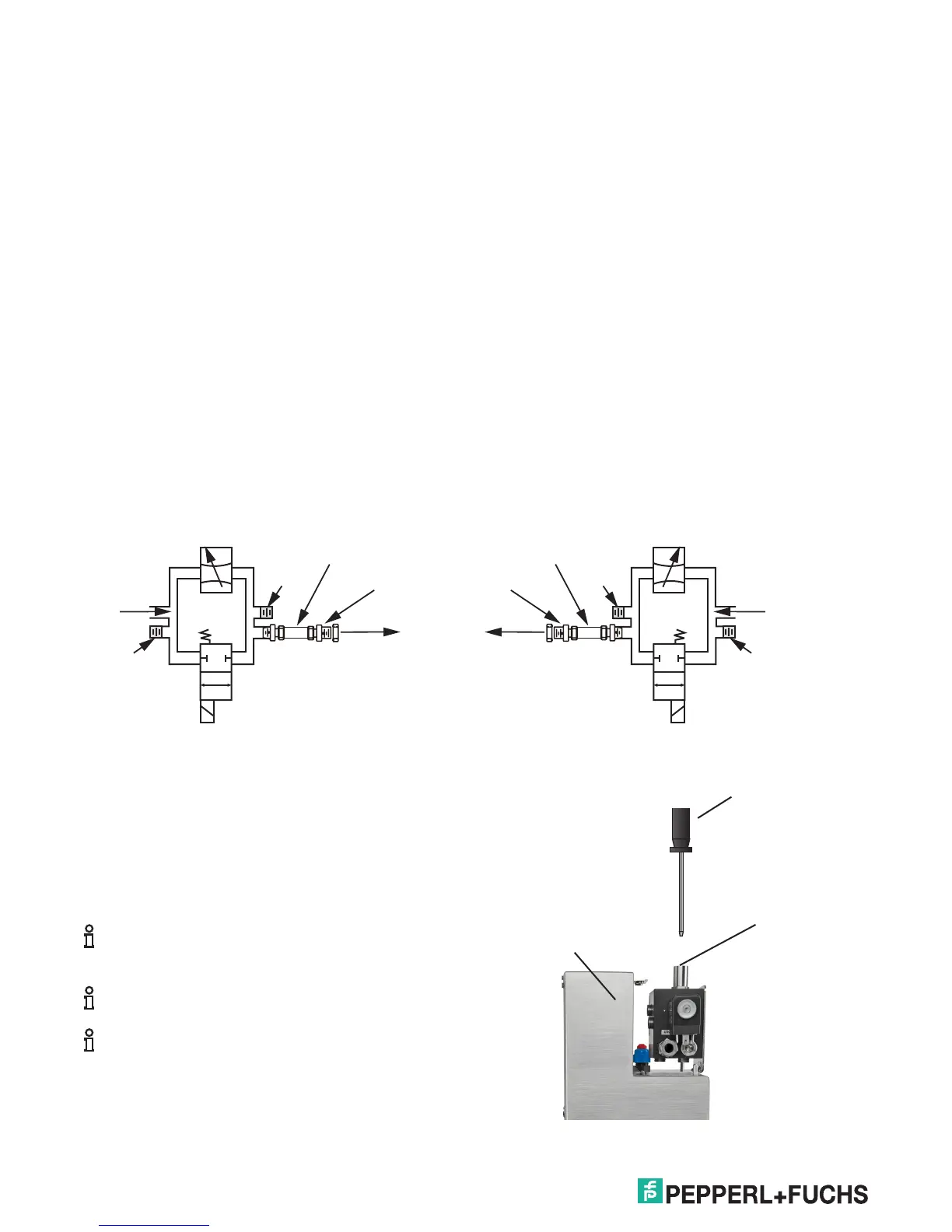
Pneumatic connections
The 6000 series system requires only two pneumatic
connections to the protective enclosure, one for the
exhaust for the vent mounting and the other for the
protective gas supply for purging and pressurization.
The vent requires a single 1 1/2" conduit knockout (Ø2"
[50.8mm]) hole in the enclosure. A lock ring with gasket
for sealing are provided. The control unit for the 6000
series provides a compression tting with a lock ring and
washer connected to a 3/8" tube. All tubing and ttings
are 316L (UNS S31603) stainless steel. A single hole
into the enclosure as noted on the mounting template will
provide the installation for this tting.
For replacement of this tubing use only 3/8" tubing with
wall thickness of 0.035" (0.9 mm).
The 6000 series control unit with the manifold can be
top, bottom, right, or left-hand mounted on the enclosure.
However, the manifold connections may have to be
reversed as shown below.
Needle valve
Plug
3/8" tubing
EFC-6-SS
Protective
gas supply
Plug
Solenoid
valve, EEx io
2/2 way
Supply
to enclosure
Needle valve
Plug
3/8" tubing
EFC-6-SS
Protective
gas supply
Plug
Solenoid
valve, EEx io
2/2 way
Supply
to enclosure
Note
Note
Counterclockwise
rotation
increases ow
Clockwise
rotation
decreases ow
Flathead screwdriver
Needle valve
in manifold
6000 control unit
housing
MAXIMUM of ve (5) turns