15
6000 Series Purge/Pressurization System
I/O Manual
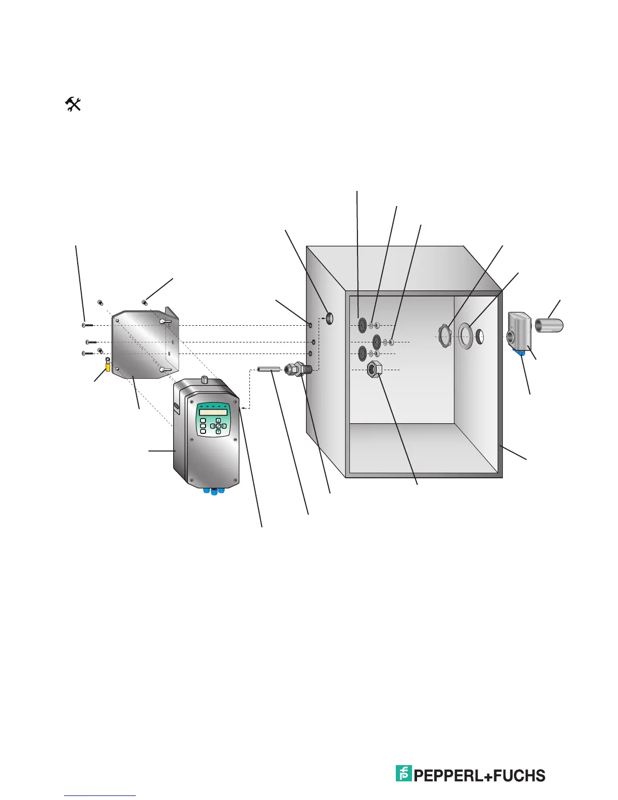
4. Put 2 of the mounting screws in the back of the
control unit to align with the key holes in the
mounting plate.
5. Hang the control unit onto the plate. Slide the unit
towards the enclosure so that the EFC-6-SS tting
is in the proper location.
6. Tighten the 2 bolts. Put the other two mounting
bolts in place and tighten.
7. Place the EFC-6-SS bolt in position and tighten.
6000 Control unit with housing "WH"
Tools:
Appropriate sized drill bits or knockout holes
1 1/16" open end box wrench
Bolts: 1/4-20 (provided),
hole clearance = 0.27" (6.86 mm) diameter
EFC-6-SS (provided):
hole clearance = 0.61" (15.54 mm) diameter
1. Drill holes using template. Check the scale if
printing an electronic version.
2. Assemble tubing and tting to control unit. Install
on the "Out" port of the correct side.
3. Bolt mounting plate to the enclosure. Type 4X
washers must be mounted inside the enclosure.
Tighten to 60 – 80 in-lb (16.38 – 18.08 Nm).
Locking nut
w/grounding screw
(included)
Seal gasket
(included)
EPV-6000
Vent cap
(included)
1/4-20 nuts (3 included)
Seal washer (3 included)
Lock washer (3 included)
EFC-6-SS (included)
Enclosure
EFC-6-SS nut (included)
3/8" stainless steel tube, 2.5" (65 mm) long (included)
3/8" ferrule tting (included)
6000 control unit
Ø 0.27" ( 6.86 mm)
hole (3x)
Ø 0.61" (15.54 mm) hole
Mounting bracket
(included)
1/4-20 pan head bolts
(3 included)
Vent cable
(included)
Grounding lug
(included)
1/4-20 pan head
w/lock washer screws
(4 included)