56
6000 Series Purge/Pressurization System
I/O Manual
Maintenance and repair
1. The 6000 purge and pressurization system
does not require special maintenance except
replacement of pneumatic lters, when used,
and normal periodic functional checks, including
pressure and ow readings within specications
contained in this manual. When checking whether
the pressure and ow measurements of the EPV-
6000 vent are within specications, use calibrated
equipment to determine measurements, or contact
a Pepperl+Fuchs representative or the factory to
send back the EPV-6000 vent for pressure and ow
verication.
2. The purge and pressurization system, when
operated in conjunction with a hazardous area,
must not be modied. If there is a defect, the
product may need to be replaced. Repairs must be
performed only by a Pepperl+Fuchs specialist who
is specically trained and authorized to repair the
defect.
3. Any replaceable fuses must be replaced with specic
fuse ratings and type, as written in this manual under
Specications.
4. When servicing, installing, and commissioning,
the area must be free of all combustible material
and/or hazardous explosive gas. Only the terminal
compartment of the control unit is accessible to the
user. Not under any circumstances, shall the control
unit, user-interface, or vent, be taken apart. The Ex d
housing cover shall only be removed when power is
removed from the device or the area is known to be
safe.
5. Any cable glands that require replacement shall be
replaced with the same model or another approved
cable gland that meets the area classication.
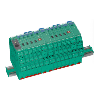
6. When replacing the EPCU, the area must be free of
hazardous gas and/or dust and power removed from
the EPCU, enclosure contacts, and auxiliary contacts.
Two screws on the bottom of the Ex d enclosure
need to be loosened but not removed. Twist the
EPCU clockwise and lift it out of the Ex d enclosure.
Reverse to install new EPCU.
Contact customer service for an RMA (return
merchandise authorization).
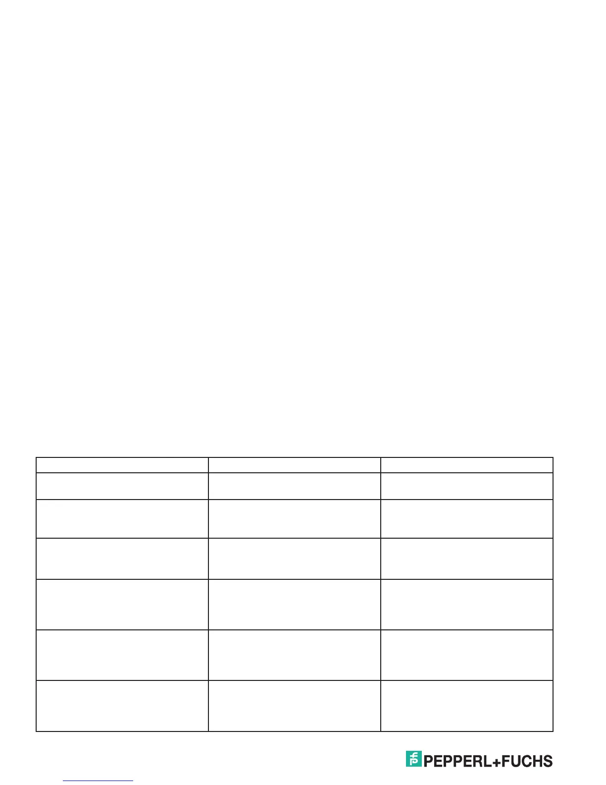
Alarm and fault conditions
The 6000 purge controller can indicate certain alarm and fault conditions when they happen. The alarm condition
is indicated on the display under the Alarm/Fault LED and will blink for an alarm and remain solid for a fault. The
alarm will not disengage enclosure contacts if they are on but can be directed to the AUX alarm contact. The fault will
disengage enclosure contacts.
Below are the alarm descriptions:
Alarm Description Cause
NO SAFE PRESSURE Enclosure pressure is below
minimum safe pressure
-No purge supply
-Enclosure leakage too great
MAX PRESSURE Enclosure pressure is above the
maximum pressure allowed
-Purge supply pressure too much
-EPV-6000 vent is blocked or not
installed
LOW PRESSURE Enclosure pressure is below the
alarm pressure but above the min.
safe pressure
-Purge supply capacity is not keeping
up
-Enclosure is starting to leak more
INPUT 1-4 BROKE/SHORT When SRM is selected, then a wire is
broken or shorted going to the switch
input
-SRM is selected and not installed on
the switch input
-Broken or shorted wire to switch/
SRM
DOOR OPEN Causes the purge system to reset
and will not start again until clear
- Signal from switch input activated
door open
-Shorted wire going to switch input
with no SRM selected
IMMEDIATE SHUTDOWN Causes the purge system to reset
and will not start again until clear
-Signal from switch input activated
immediate shutdown
-Shorted wire going to switch input
with no SRM selected