Do you have a question about the Pepperl+Fuchs K-System and is the answer not in the manual?
Details the information provided in the document for product lifecycle stages.
Specifies qualified personnel for product operation and maintenance.
Explains warning symbols (Danger, Warning, Caution) and informative symbols (Note, Action).
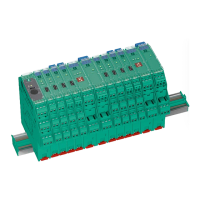
Describes isolated barriers for intrinsically safe circuits in hazardous areas.
Details KC (12.5 mm), KF (20 mm), and KH (40 mm) housing widths.
Explains removable terminal blocks for simplified connection and cabinet assembly.
Explains the meaning of green, black, gray, and blue color identification on devices.
Details the meaning of Green, Red, and Yellow LEDs for status indication.
Lists and describes DIP switches, rotary switches, and potentiometers for device configuration.
Explains the label carrier fitted on the front side for individual identification.
States that devices are mounted on a 35 mm DIN mounting rail per EN 60715.
Explains the Power Rail as an optimum solution for reducing wiring and installation costs.
Covers explosion hazards from components, pollution, and electric shock during mounting.
Provides instructions for connecting devices, including terminal blocks, field, and control sides.
Instructs to set operating elements as described in the datasheet section.
Explains fault monitoring capabilities for line faults and device faults.
Details how faults are transmitted via LEDs, fault indication outputs, and collective error messages.
Details standard signals like 0/4-20 mA and 0/2-10 V and NAMUR NE43.
Provides instructions for dismounting the isolator from the DIN mounting rail.
Lists electrical, safety, environmental, mechanical, and conformity data for the devices.
Explains the structure and meaning of model number positions for K-System devices.
Provides physical dimensions for various housing types of K-System isolated barriers.
| Mounting | DIN Rail |
|---|---|
| Output | Relay |
| Protection Class | IP20 |
| Housing Material | Plastic |
| Signal Type | Digital |
| Number of Channels | 2 |
| Safety Integrity Level | SIL 3 |
| Operating Voltage | 24 V DC |
| Ambient Temperature | -20 ... 60 °C (-4 ... 140 °F) |
| Connection Type | Screw terminals |