2020-12
16
K-System – Isolated Barriers
Product Specifications
2.5 Status Indicators of the Isolators
LEDs are often used on isolators to indicate different statuses (e. g. for power supply,
device failure, status messages, binary switching states). Standard LED colors are assigned
to the status display according to NAMUR NE44.
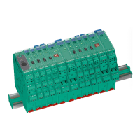
Figure 2.14 Example status indicators
LED Display function Display Meaning
Green LED Power supply On Power supply OK
Off No power supply or insufficient power supply – device
faulty
Red LED Device fault, device
failure
On Internal fault signal, failure signal – fault/failure display
of causes detected inside the device, device needs
replacing
Line fault Flashing External fault signal, failure signal – fault/failure display
of causes detected outside the device, inspection
and elimination of fault required
No fault Off No malfunction, device is operating properly
Yellow LED Switching states of
binary inputs and
outputs
On Possible causes of the output:
• The relay is energized.
• The NO contact (also a change-over contact)
is actively closed.
• The open collector is switched through.
• The switching voltage generated inside the device
is applied.
Possible causes of the input:
• A binary switching signal is present.
• An analog limit value is reached.
Off Possible causes of the output:
• The relay is de-energized.
• The NO contact (also a change-over contact)
is actively opened.
• The open collector is not switched through.
• The switching voltage generated inside the device
is not applied.
Possible causes of the input:
• A binary switching signal is present.
• An analog limit value is reached.
Table 2.1 Meaning of status indicators
1 Yellow LED "OUT"
Switching state of the output
2 Red LED "CHK"
Lead breakage and short circuit status indicator
3 Green LED "PWR"
Power supply status indicator