2017-04
14
Functional Safety KFD2-SH-Ex1(.T)(.OP), KHA6-SH-Ex1
Planning
KFD2-SH-Ex1
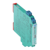
Parameters acc. to IEC 61508 Characteristic values
Assessment type and
documentation
FMEDA, proven-in-use assessment, certificate
Device type A
Mode of operation Low Demand Mode or High Demand Mode
HFT 0
1
1
The redundant relays can be considered as elements with hardware fault tolerance. For this calculation the
redundant relays were considered as "diagnostics" for the relay with a DC value of 99 % to take care of a
possible common cause failure.
0
SIL 3 (proven-in-use) 2 (proven-in-use)
Safety function Output I is de-energized when
input in low state
Output II is de-energized when
input in low state
s
237 FIT 203 FIT
du
0.6 FIT 51.9 FIT
dd
50.5 FIT 36.6 FIT
no effect
2
2
"Annunciation failures" are not directly influencing the safety functions and are therefore added to the
no effect
value.
215 FIT 156 FIT
total (safety function)
288 FIT 291 FIT
SFF 99.8 % 82 %
MTBF
3
3
acc. to SN29500. This value is calculated with the failure rates of the device components which are part of the
safety function of the device.
204 years 254 years
MTTF
d
2240 years –
DC
d
98.7 % (medium) –
B10
d
250000 –
Category (ISO 13849-1) 3 –
PL d –
PFH 6.47 x 10
-10
1/h 5.19 x 10
-8
1/h
PFD
avg
for T
1
= 1 year 2.83 x 10
-6
2.27 x 10
-4
PFD
avg
for T
1
= 2 years 5.67 x 10
-6
4.55 x 10
-4
PFD
avg
for T
1
= 5 years 1.42 x 10
-5
1.14 x 10
-3
Reaction time
4
4
Time between fault detection and fault reaction.
< 30 ms < 30 ms
Table 3.2