2020-05
14
Functional Safety KFD2-SR2-Ex*.W(.LB)
Planning
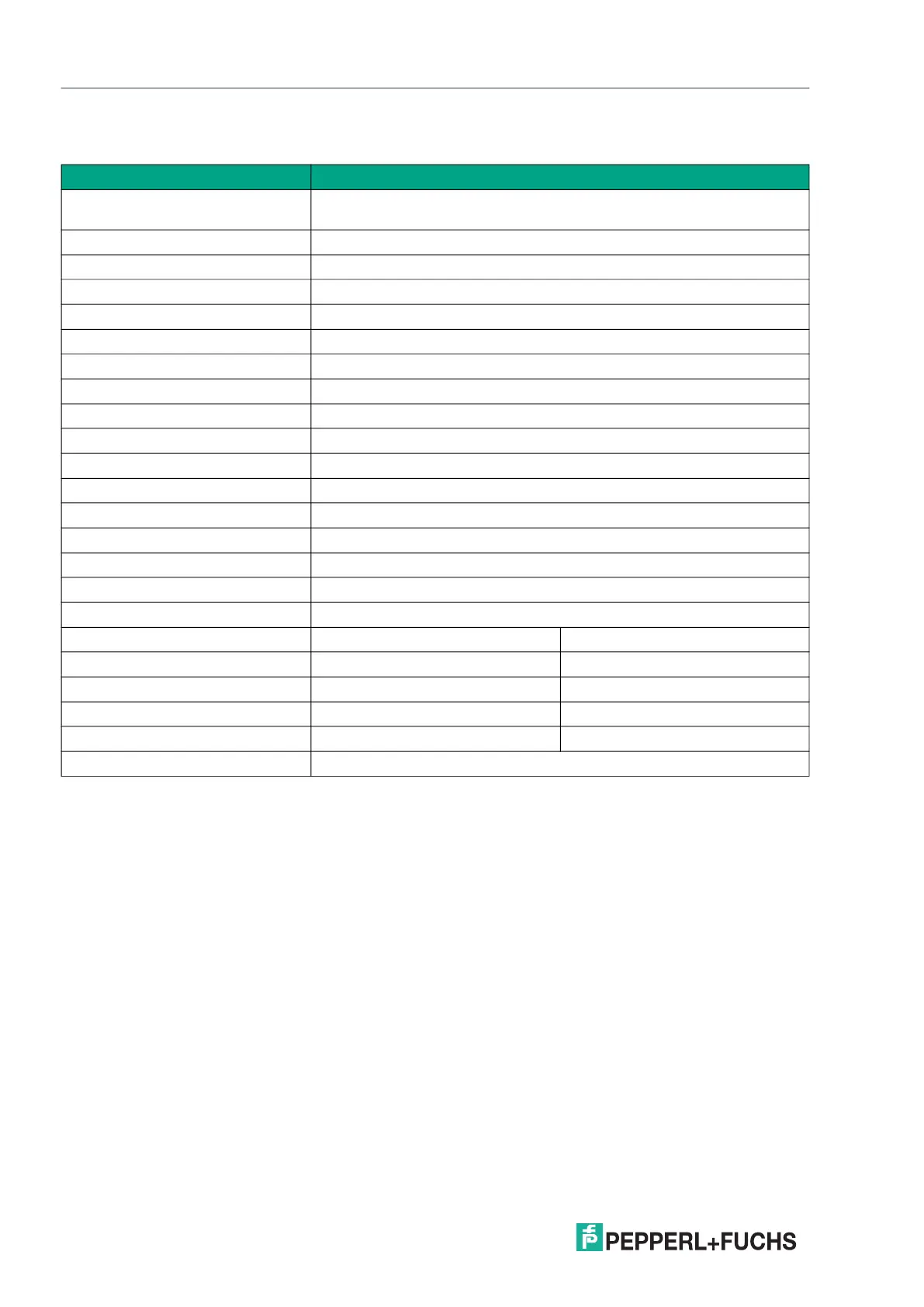
3.4 Characteristic Safety Values
The characteristic safety values like PFD, SFF, HFT and T
1
are taken
from the SIL report/FMEDA report. Observe that PFD and T
1
are related to each other.
The function of the devices has to be checked within the proof test interval (T
1
).
Parameters Characteristic values
Assessment type and
documentation
Full assessment
Device type A
Mode of operation Low demand mode or high demand mode
HFT 0
SIL 2
SC 2
Safety function Output is de-energized
s
1
113 FIT
dd
0 FIT
du
37.8 FIT
total (safety function)
1
151 FIT
no part
127 FIT
SFF 75 %
DC 0 %
MTBF
2
288 years
MTTF
D
3023 years
PFH 3.77 x 10
-8
1/h
Test version Manual proof test In-loop proof test
PTC 100 % 90 %
PFD
avg
for T
1
= 1 year
3
1.65 x 10
-4
3.15 x 10
-4
PFD
avg
for T
1
= 2 years
3
3.31 x 10
-4
4.64 x 10
-4
PFD
avg
for T
1
= 3 years
3
4.96 x 10
-4
6.13 x 10
-4
Fault reaction time
4
< 20 ms
Table 3.1
1
"No effect failures" are not influencing the safety function and are therefore not included in SFF and in the failure rates
of the safety function.
2
acc. to SN29500. This value includes failures which are not part of the safety function/MTTR = 8 h. The value is calculated
for one safety function of the device.
3
Since the current PTC value is < 100 % and therefore the probability of failure will increase, calculate the PFD value according
to the following formula:
PFD
avg
= (
du
/ 2) x (PTC x T
1
+ (1 – PTC) x T
service
)
A service time T
service
of 10 years was assumed for the calculation of PFD
avg
.
4
Step response time, also valid under fault conditions (including fault detection and fault reaction)