2014-09
16
Safety Manual SIL KFD2-ST*4-(Ex)*, KFD2-CR4-(Ex)*
Proof Test
Proof Test for all Channels
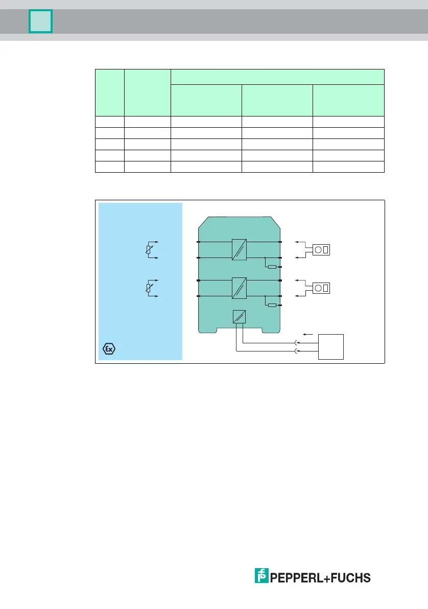
Figure 4.1 Proof test set-up for KFD2-CR4-(Ex)* and KFD2-STC4-(Ex)*
Usage in Zone 0, 1, 2/Div. 1, 2 only for Ex versions
For KCD2-CR4-(Ex)1 and KFD2-STC4-(Ex)1 do not regard the second channel.
Step
No.
Set input
value (mA)
Measurement point
Output value (mA)
for STC4 and CR4
devices
Output value (V) for
STV4 devices,
-1 version
Output value (V) for
STV4 devices,
-2 version
1 20.0 20.0 ± 0.4 5.0 ± 0.1 10.0 ± 0.2
2 12.0 12.0 ± 0.4 3.0 ± 0.1 6.0 ± 0.2
3 4.0 4.0 ± 0.4 1.0 ± 0.1 2.0 ± 0.2
4 23.0 23.0 ± 0.4 5.75 ± 0.1 11.5 ± 0.2
5 0 < 0.2 < 0.1 < 0.1
Table 4.1
KFD2-STC4-Ex2
Zone 0, 1, 2
Div. 1, 2
Zone 2
Div. 2
I
supply
3-
1+
6-
4+
7-
8+
9
250 Ω
10-
11 +
12
250 Ω
Multimeter
(mA)
Multimeter
(mA)
Signal calibration
4 mA ... 20 mA
14+
15-
24 V DC
Power
supply
www.acornfiresecurity.com
www.acornfiresecurity.com