Safety Manual SIL KFD2-ST*4-(Ex)*, KFD2-CR4-(Ex)*
Proof Test
2014-09
17
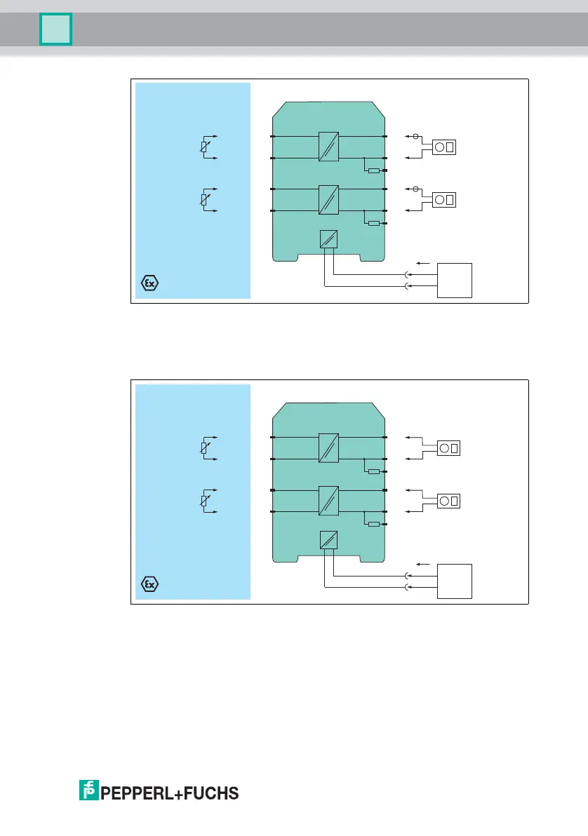
Figure 4.2 Proof test set-up for KFD2-STC4-(Ex)*-3 and KFD2-STC4-(Ex)*-Y*
Usage in Zone 0, 1, 2/Div. 1, 2 only for Ex versions
For KFD2-STC4-(Ex)1-3 and KFD2-STC4-(Ex)1-Y* do not regard the second
channel.
Figure 4.3 Proof test set-up for KFD2-STV4-(Ex)*-1 and KFD2-STV4-(Ex)*-2
Usage in Zone 0, 1, 2/Div. 1, 2 only for Ex versions
For KFD2-STV4-(Ex)1-1 and KFD2-STV4-(Ex)1-2 do not regard the second
channel.
KFD2-STC4-Ex2-3
Zone 0, 1, 2
Div. 1, 2
Zone 2
Div. 2
I
supply
3-
1+
6-
4+
7-
8+
9
250 Ω
10-
11 +
12
250 Ω
Multimeter
(mA)
Multimeter
(mA)
Signal calibration
4 mA ... 20 mA
14+
15-
24 V DC
Power
supply
KFD2-STV4-Ex2-2
Zone 0, 1, 2
Div. 1, 2
Zone 2
Div. 2
I
supply
3-
1+
6-
4+
7-
8+
9
250 Ω
10-
11 +
12
250 Ω
Multimeter
(V)
Multimeter
(V)
Signal calibration
4 mA ... 20 mA
24 V DC
Power
supply
14+
15-
www.acornfiresecurity.com
www.acornfiresecurity.com