1/01 E Service Instructions 14
Machine Size 168 (Fig.18)
Knife beam 1 moves between the
slide surfaces on machine frame
2 and guide strips 3. On top, the
guide strips rest on two stud bolts
4 each and are fixed to the ma-
chine frame by two nuts 5.
Below, the guide strips are sup-
ported on the machine frame by
four threaded bushes 6 and are
fastened to the frame by screws
7.
Gap s should be < 0.05 mm.
Checking the play:
• Push the knife beam (without
knife) against the frame from the
rear at the top and bottom posi-
tions. Use a feeler gauge to check
the play between the knife beam
and the guide strip on the left and
right sides.
If required, readjust gap s as
follows:
• Remove the light guards and the
upper lateral paneling.
• Set the knife beam to medium
feed height and push it against
the frame.
• Slacken nuts 5 and screws 7.
• Use nuts 5 and threaded bushes
6 to adjust the play.
• Lock nuts 5 and tighten screws
7 and check the play once again
at the topmost and lowermost
positions of the knife beam on the
left and right of the guide strip.
Correct, if required.
• Re-fit the paneling and the light
guards.
Important: Check the light
guards for proper functioning.
Checking the play:
• Push the knife beam (without
knife) against the frame from the
rear at the top and bottom posi-
tions. Check the play between
the knife beam and the guide
strip on the left and right sides
using a feeler gauge.
If required, readjust gap s as fol-
lows:
• Set the knife beam to medium
feed height and push it against
the frame.
• Remove the front paneling.
• Slacken clamping screws 8 on
the left and right of the cutting
table (8 screws in total).
• Remove plastic cover 7 and
adjust guide strip 3 against the
knife beam with adjusting screws
6 until the required play is ob-
tained.
• Re-tighten clamping screws 8
and check the play at the knife
beam top and bottom positions
once again.
• Re-fit the front paneling.
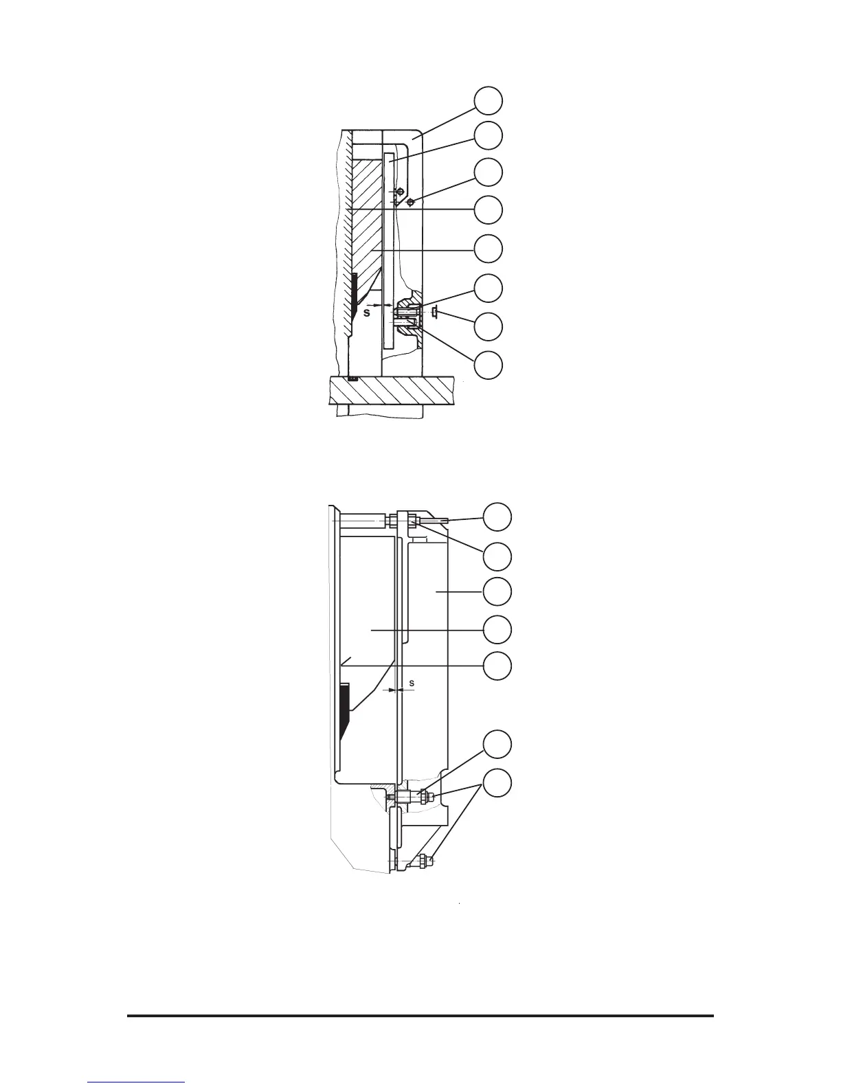
Machine Sizes 115/132 (Fig. 17)
Knife beam 1 moves between
slide surfaces 2 on the machine
frame and guide strips 3. The
guide strips are supported in
machine front part 5 by guide pins
4. By means of adjusting screws
6 located under plastic covers 7
on the machine front parts, the
guide strips can be moved towards
the knife beam. On the cutting
table side, guide pins 4 and
adjusting screws 6 are secured
against moving or turning by
clamping screws 8.
Gap s should be < 0,05 mm .
Fig. 17
5
3
8
2
1
6
7
4
Fig. 18
5
3
2
6
7
4
1