I -
4 5
IV - Getting started
1
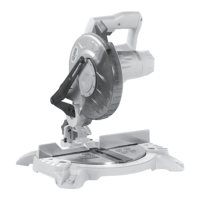
ACCESSORIES
The tool is supplied with the following
accessories:
• Hex key, 6mm
• Ø210mm x 30mm x 24T blade (fitted)
• Dust bag
We recommend that you purchase your
accessories in the store from where you
obtained the tool. Use good quality accessories
and the brand recommended by the vendor.
Sales staff will help and offer advice.
2
UNPACKING
Due to modern mass production techniques, it
is unlikely that your power tool is faulty or that
a part is missing. If you find anything wrong, do
not operate the tool until the parts have been
replaced or the fault has been rectified. Failure
to do so could result in serious personal injury.
Remove all loose parts from the carton.
Remove the packing materials from around the
saw.
Using the operating handle (3) carefully lift the
saw from the carton and place it on a level work
surface.
The saw has been shipped with the saw arm
locked in the down position.
To release the saw arm, push down on the top
of the saw arm, pull on the release knob (2),
rotate it 90° and release it.
Slowly raise the saw arm.
WARNING. Do not lift the saw whilst holding on
to the guards. Use the operating handle (3).
3
TRANSPORTATION
Lift the mitre saw only when the saw arm is
locked in the down position, the saw is switched
off and the plug is removed from the power
socket.
Only lift the saw by the operating handle (3)
or outer castings. Do not lift the saw using the
guards.
4
BENCH MOUNTING
The saw base has holes in each corner to
facilitate bench mounting.
Place the saw on a level, horizontal bench or
work table using bolts (not supplied) and fix the
saw to the bench using 4 bolts.
If desired, you can mount the saw to a piece
of 13mm or thicker plywood which can then
be clamped to your work support or moved to
other job sites and re-clamped.
CAUTION. Make sure that the mounting surface
is not warped as an uneven surface can cause
binding and inaccurate sawing.
5
RELEASE KNOB
The release knob (2) is provided for holding the
cutting head down whilst transporting or storing
the mitre saw. The saw must never be used with
the release knob locking the head down.
6
MITRE TABLE LOCKS
The mitre table locks (15) are used to lock the
table at the desired mitre angle.
The mitre saw cuts from 0° to 45° both left and
right.
To adjust the mitre angle loosen the mitre table
locks and rotate the mitre table to the desired
position.
The mitre table features positive click stops at
0°, 15°, 22.5°, 30° and 45° for quick setting of
common mitre angles.
WARNING. Be sure to tighten the mitre table
locks before making a cut. Failure to do so
could result in the table moving during the cut
and cause serious personal injury.
7
BEVEL LOCK
The bevel lock (7) is used to set the blade at the
desired bevel angle. The mitre saw bevel cuts
from 0° to 45° to the left. To adjust the bevel
angle loosen the bevel lock and adjust the saw
arm to the desired bevel angle.
WARNING. Be sure to tighten the bevel lock
before making a cut. Failure to do so could
result in the saw arm moving during the cut and
cause serious personal injury.
4 5
4
Symbols
The rating plate on your tool may show symbols. These
represent important information about the product or
instructions on its use.
Wear hearing protection.
Wear eye protection.
Wear respiratory protection.
Double insulated for
additional protection.
Conforms to relevant
safety standards.
Waste electrical products should not be disposed
of with household waste. Please recycle where
facilities exist. Check with your Local Authority or
retailer for recycling advice.
Read the instruction manual.
 Loading...