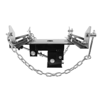
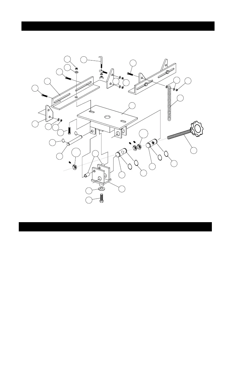
Assembly Diagram
1
14
14
15
15
16
18
16
14
14
20
15
16
17
10
19
2
11
11
13A
21
12
3
4
5
6
7
8
9
13B
1. Install Threaded Bushing (3), into holes in Platform (1) using Large
Snap Rings (11) as shown.
2. Screw Adjustable Tilt Knob (2) through threaded bushing approximate-
ly half way.
3. Install 2 Lock Nuts (13A) approximately 3” from end of threaded shaft.
4. Install Non-Threaded Bushing (4) into holes in Pivot Frame (5) using
Large Snap Rings (11) as shown.
5. Slide Non-Threaded Bushing over onto threaded shaft and install
remaining Lock Nut (13B).
6. Connect Platform (1) to Pivot Frame (5) using Pivot Pin (6), Small Snap
Rings (12) and Spacers (21) as shown.
7. Bolt on Mounting Bracket Frames (7) and Mounting Brackets (8).
8. Install Chain Hook Assembly (9) and Safety Chain (10) as shown.
9. Install Assembled Adaptor onto Service Jack Saddle Frame securing
with Bolt (14) and Washer (20).
ASSEMBLY INSTRUCTIONS