3. Disconnect the J1/P1 and J2/P2 connectors from
the ECM. Move the harness to a position that will
not allow the harness to accidentally move back
and make contact with any of the ECM pins.
Illustration 37 g01143634
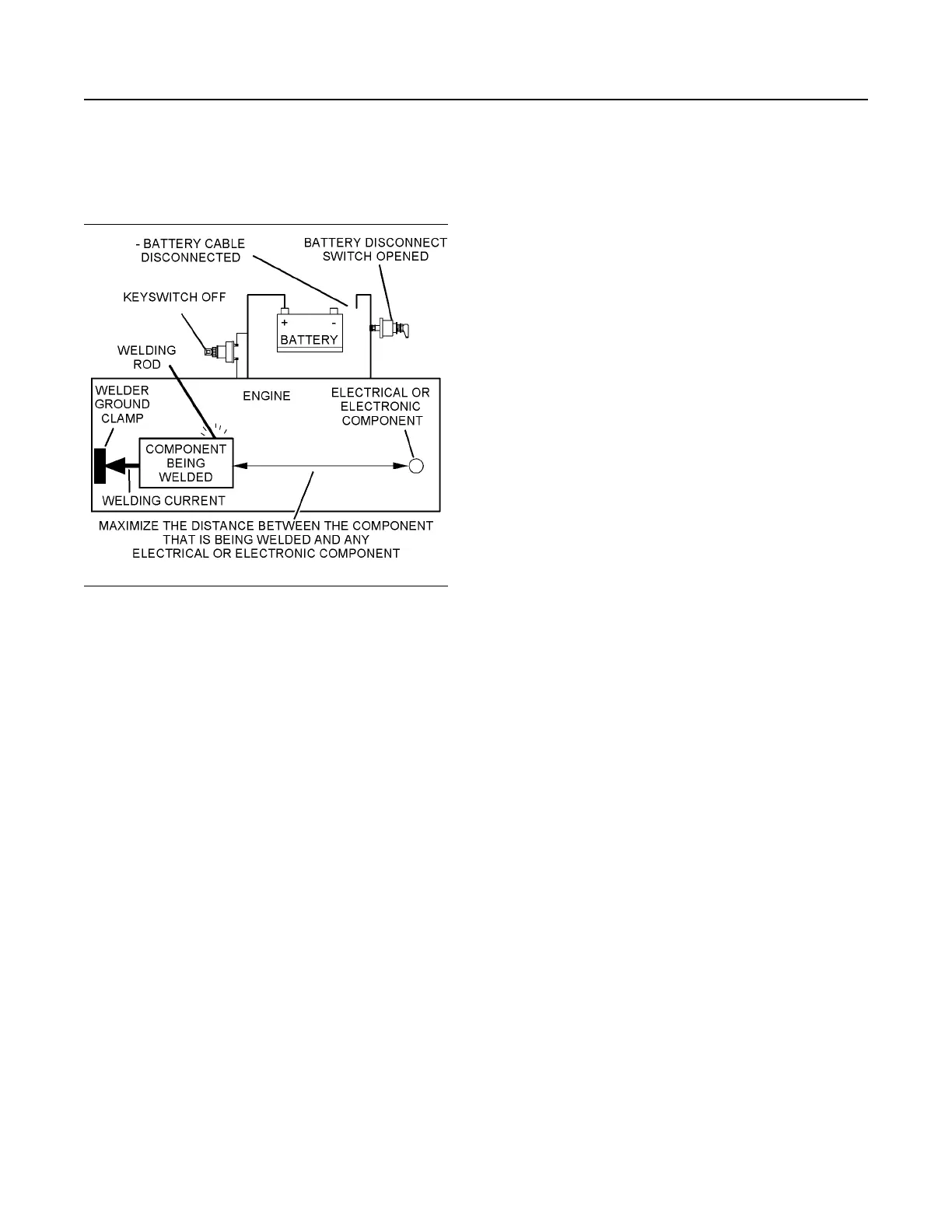
4. Connect the welding ground cable directly to the
part that will be welded. Place the ground cable as
close as possible to the weld in order to reduce the
possibility of welding current damage to bearings,
hydraulic components, electrical components, and
ground straps.
Note: If electrical/electronic components are used as
a ground for the welder, or electrical/electronic
components are located between the welder ground
and the weld, current flow from the welder could
severely damage the component.
5. Protect the wiring harness from welding debris and
spatter.
6. Use standard welding practices to weld the
materials.
SEBU8311-09
59
Maintenance Section
Welding on Engines with Electronic Controls