BRZ/ FRS/ GT-86 Master Cylinder Brace
2014-09-23
Thank you for purchasing this PERRIN product for your car! Installation of this product should only be performed by persons experienced with installation of aftermarket performance parts
and proper operation of high performance vehicles. If vehicle needs to be raised off the ground for installation, the installer must use proper jacks, jack-stands and/or a professional
vehicle hoist for safety of the installer and to protect property. If the vehicle is lifted improperly, serious injury or death may occur! Please read through all instructions before performing
any portion of installation. If you have any questions, please contact our tech department prior to starting installation. We can be reached in any of the following methods:
Email Tech@PERRINperformance.com
Instant Chat off the main page of www.PERRINperformance.com
Or simply call our tech team at 503-693-1702
GENERAL MODIFICATION NOTE
Modifications to any vehicle can change the handling and performance. As with any vehicle extreme care must be used to prevent loss of control or roll-over during sharp turns or abrupt
maneuvers. Always wear seat belts, and drive safely, recognizing that reduced speeds and specialized driving techniques may be required. Failure to drive a vehicle safely may result in
serious injury or death. Do not drive a vehicle unless you are familiar with its unique handling characteristics and are confident of your ability to maintain control under all driving
conditions. Some modifications (and combinations of modifications) are not recommended and may not be permitted in your state or country. Consult the owner’s manual, service
manual, instructions accompanying these products, and local laws before purchasing and installing these modifications. You are responsible for the legality and safety of the vehicle you
modify using these components.
SPECIAL NOTES:
The use of a factory service manual is highly recommended. These can be purchased or downloaded online at http://techinfo.subaru.com.
This part only fits on left hand drive vehicles.
Parts Included with the PERRIN Master Cylinder Brace:
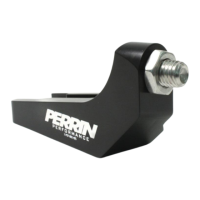
(1) BRZ/FR-S Master Cylinder Support Bracket
(1) M5 Allen Wrench
(1) M6 Allen Wrench
(1) M6 SS washer
(2) M6x20 Socket Cap Screw
(1) M12x30 SS set screw
(1) M12 SS jam nut
Installation of PERRIN Master Cylinder Brace
1. Locate fuel line junction on left side of vehicle. NOTE: 3 fuel hoses attach to black plastic mount, and snaps into steel bracket that is bolted to shock tower.
2. Using long needle nose type pliers, squeeze back side of plastic clip to free from steel bracket.
3. Move (3) fuel lines (leaving plastic bracket attached) toward engine to gain room to install PERRIN Master Cylinder Support.
4. Using 10mm socket or wrench remove fuel line bracket to shock tower. NOTE: This will be reinstalled in later steps.
5. Locate and remove (2) black stickers toward the left of where fuel line bracket was located. NOTE: These are covering up two holes that will be used.
6. Install supplied M12 set screw and jam nut into PERRIN Master Cylinder Support as shown below. NOTE: Hex head is facing other direction from this angle.