TB 100
PAG. 14 Cod. 29050055 Rev.01 Edit: 09/2015
4.1.8b Connect the drive shaft to the tractor's PTO and then to the machine, whilst
making sure that the direction of rotation is identical, as indicated on the shaft, until
the buttons spring out into their correct locations. Secure all connection points with
the safety chains.
4.1.9b Make sure that the machine is level and properly secured to the tractor's PTO.
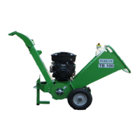
4.1c Fitting the hydraulic version of the machine
4.1.1c Connect the machine to the appropriate connection point (optional - on request)
4.1.2c Connect the hydraulic tubes to the tractor.
NOTA BENE: With regard to powering the hydraulic version, it is recommended to have
the tractor of 40 lt/min capacity. Maximum pressure may not exceed 250 bar.
CAUTION!
The infeed chute may not be used at less than 600 mm above ground (Fig. 3.4.3)
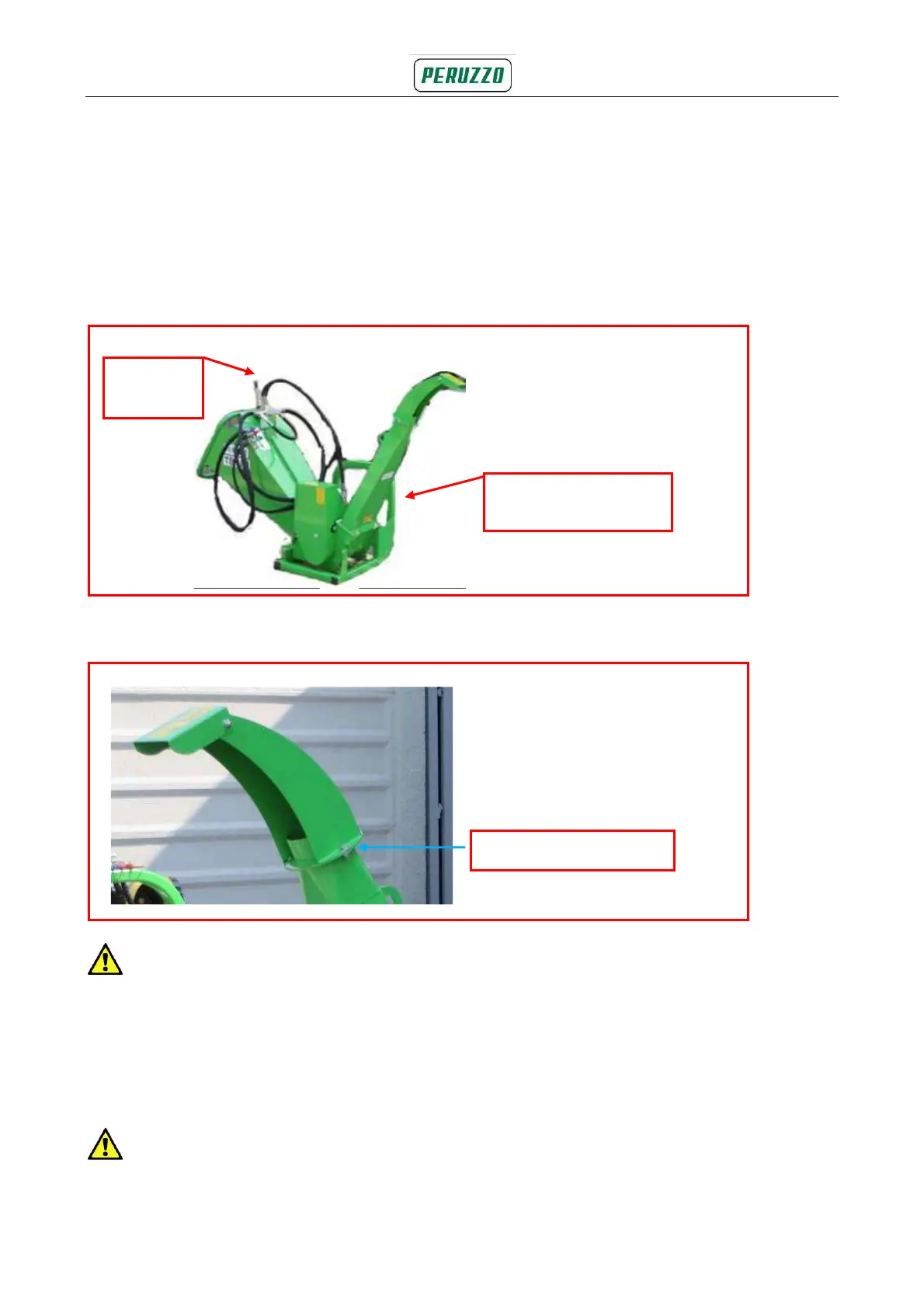
4.3 Discharge Chute (Fig 4.3)
4.3.1 Release the spout clamp, remove and reset the spout in the desired direction and
tighten the clamp.
4.3.2 Set the flap at the desired height.
CAUTION!
Observe wind direction - avoid danger of discharge being blown towards the operator.
Fig. 4.3 Discharge chute
Fig. 4.1b Attachment for the hydraulic version
Control
lever
Attachable loader
(optional)
Spout bolts