TB 100
PAG. 13 Cod. 29050055 Rev.01 Edit: 09/2015
4.0 Getting the machine ready for work
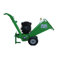
4.1a Initial fuelling and parking
4.1.1a Position the machine on the level ground and ensure the stand is secure
(Fig 4.1a). Secure the machine support with an appropriate safety pin (Fig. 4.1a).
4.1.2a Fill the fuel tank with petrol.
4.1.3a Check the engine oil level.
4.1.4a Check that the STOP button is released.
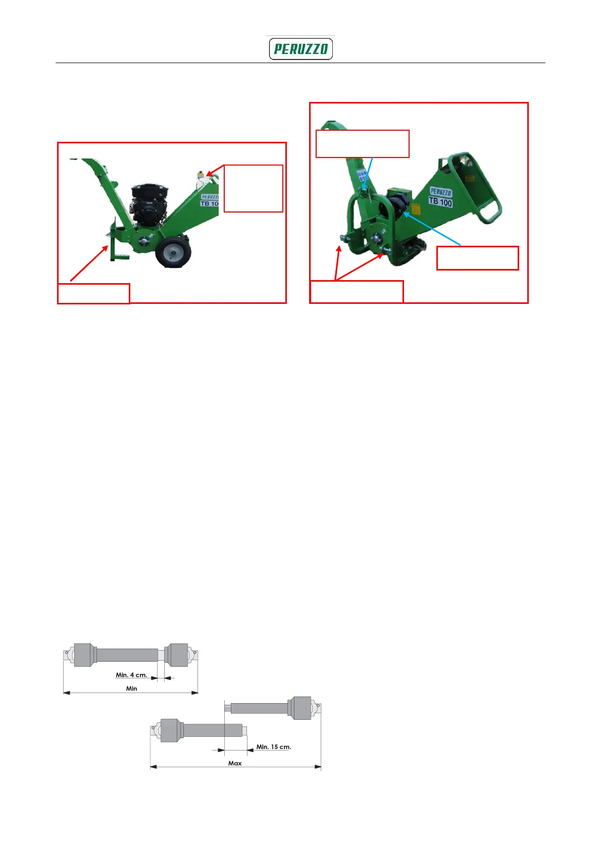
4.1b Fitting the machine to the tractor
4.1.1b Remove the top, and lower the linkage pins on the chipper (Fig 4.1b)
4.1.2b Lower the three-point linkage on the tractor and reverse up to the chipper.
4.1.3b Insert each tractor lower lift arm in the corresponding clevis on the frame,
and insert each lower linkage pin.
4.1.4b Secure the pins with the clips provided.
4.1.5b Adjust the top link to the correct length and insert the linkage pin through
the frame, then secure with the clips provided.
4.1.6b Switch off the tractor engine.
4.1.7b Check that the PTO shaft is of the correct length. When fully retracted,
the distance between the two parts must not exceed 4 cm, when fully extended,
the two parts must overlap by no less than 15 cm; see the figure further below.
Fig. 4.1b Tractor coupling and PTO
Fig. 4.1a Support and discharge chute
PTO shaft
Lower link pin
STOP
button
Upper link pin