7
ENGLISH
ENGLISH
6
INSTALLATION INSTRUCTIONS FOR D9, W9, PC12, PC13 MODELS
These doors are simple to install by any handy man with common DIY power tools. Or you
can employ the services of a professional should you feel the installaon may be beyond your
experience.
Important:
Please read the instrucons in full before you proceed to install. Should you decide to install the
door by yourself, it is important that the appropriate safety gear is worn such as protecve eye
wear.
Disclaimer:
It is vital that prior to installaon you have your wall or door checked to ensure that there are
no plumbing or electrical wires or devices in the vicinity which may result in injury, fatality or
damage in the event of contact.
It is the responsibility of the person installing this door that they ensure the appropriate safety
gear and equipment are used in accordance with recommended safety procedures and local
safety requirements.
Pet doors may increase the risk associated with unwanted pets or intruders. We will not be liable
for any damage or injury that may be caused as a result of the installaon.
Children:
For child safety we do not recommend that the door be installed in any area where a child could
have access to an unfenced or unprotected swimming pool or pond.
Please read the instrucons carefully prior to installing the pet door. Ensure that your pet will t
through the pet door prior to Installaon.
DOOR FLAP REMOVAL
In the event that you need to remove the door ap/s from your pet door, follow the instrucons
below and refer to the images on page 3.
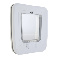
D9: Remove the two screws at the top of the ap, un-clip the top of the ap by pulling out and
upward. The ap is now loose and may be taken out. Installaon is the opposite to removal.
Make sure the ap ‘clips’ in securely (as illustrated in Figure D9).
PC12: Please read the PC12 operang instrucon manual for detailed instrucons.
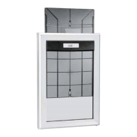
PC13: Using a small at head screw driver release the door hinge whilst gently pulling the door
out of the frame. You will be able to li the door out of the other hinge socket. To install a door,
insert one hinge into it’s socket and depress the other hinge as you push it into the frame in
order for it to spring into it’s socket. (as illustrated in Figure PC13).
INSTALLATION STEPS:
STEP 1. Chose the area that best suits your installaon.
STEP 2. Mark out the preferred area (as illustrated in Figure 1).
The recommended height should be to have the top of the pet door opening (ap) level
with the shoulder height of your pet (as illustrated in Figure 2).
Take outside measurement of the inner frame of the door and add another ¼” (4-5 mm)
to both width and height. This will provide sucient installaon clearance.
For PC12 you may need to make allowance for cables. (refer to PC12 Instrucon Manual
for details).
STEP 3. Once you have marked up the cut-out measurement, draw a line around the perimeter
using a pencil (as illustrated in Figure 1).
Drill a hole in each of the four inside corners using a minimum of 3/8’ (10mm) drill bit
(as illustrated in Figure 3).
Using a reciprocang jigsaw, proceed to cut out the opening for the pet door by cung
along the pencil line (as illustrated in Figure 4).
For walls cut out the internal opening rst. Remove any insulaon and place the door
into the opening. Ensure the door is level then mark the hole from the inside and
proceed to drill holes from the inside of the door through to the outside.
This will help prevent any misalignment with the outside wall. Depending upon the
locaon of the opening it may require lining with mber to provide addional support
for the door. Do not clamp the door against plasterboard only.
STEP 4. Once the hole is fully prepared, take the internal secon of the door and place a
generous bead of construcon silicon around the parameter of the frame leg (as
illustrated in Figure 5).
Now place a generous bead of silicon on the walls around the cut out to provide a
weather seal (as illustrated in Figure 6).
STEP 5. Now insert the inner and outer frame into the cut out and clamp ghtly together using
builders clamps. (as illustrated in Figure 7 & 8).
Double check that the frames are level.
STEP 6. Next aach both the inner and outer frames together using screws or pop rivets
provided. Pre drill holes for rivets with a 1/8” (3 mm) drill and ensure that they are
evenly distributed. (as illustrated in Figure 9 & 10).
STEP 7. Next place an addional silicon bead around the frame of the door to provide a
nice neat nish and also around the internal joint in the internal pet door frame. (as
illustrated in Figure 11 & 12).
 Loading...